Light emitting element drive device and display apparatus

a technology of drive device and light emitting element, which is applied in the direction of electric variable regulation, process and machine control, instruments, etc., can solve the problems of large loss, poor luminance and noise resistance, and large loss, etc., to achieve stable adjustment of luminance, wide dynamic range, and wide dynamic range

Active Publication Date: 2007-12-25
SATURN LICENSING LLC
View PDF9 Cites 68 Cited by
  • Summary
  • Abstract
  • Description
  • Claims
  • Application Information

AI Technical Summary

Benefits of technology

[0009]An object of the present invention is to provide a light emitting element drive circuit and a display system able to simultaneously perform constant current control and PWM control and able to perform stable adjustment of the luminance in a wide dynamic range.
[0014]Preferably, the constant current use reference voltage source can change the value of the constant current use reference voltage output by an external signal and can adjust the luminance of the light emitting element by changing the current value when the switch means is ON.
[0020]According to the present invention, simultaneous constant voltage control and PWM control becomes possible, and stable adjustment of luminance in a wide dynamic range becomes possible. Further, by making the current value when controlling the constant current variable, adjustment of the luminance in a further broader dynamic range becomes possible. Further, a current restricting resistor is not used for the control of the constant current, and a resistor having a low resistance can be used as the current detection resistor, therefore highly efficient drive of an LED becomes possible.

Problems solved by technology

In the system of FIG. 1, however, with a high luminance LED through which a large current is passed, the loss due to this resistor 3 becomes an issue.
However, the smaller the current, the smaller the potential difference, so the worse the luminance and the greater the susceptability to noise etc.
Further, when the resistance value is made large enough that a sufficient voltage is obtained even with a small current, there is the disadvantage that the loss becomes large at the time of a large current.
However, when using a constant current source as a drive device employing the PWM control system, it is attempted to create a constant flow of current at a constant current source irrespective of the fact that the current does not flow in the OFF period, therefore the control becomes abnormal and there is the apprehension that correct constant current control can no longer be carried out.
As a result, there is the disadvantage that stable adjustment of the luminance adjustment is not possible.

Method used


Image

  • Light emitting element drive device and display apparatus
  • Light emitting element drive device and display apparatus
  • Light emitting element drive device and display apparatus

Examples


first embodiment

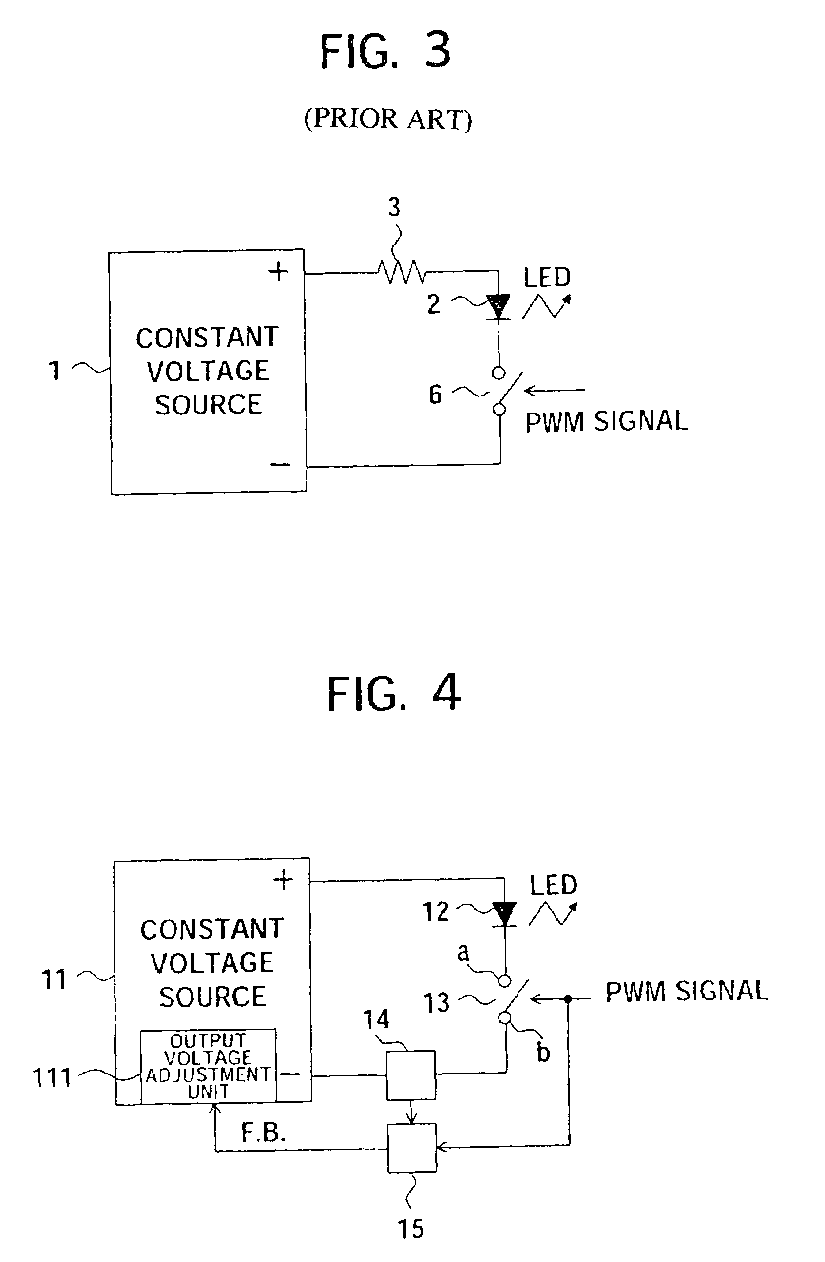
[0037]FIG. 4 is a circuit diagram of a light emitting element (LED) drive device according to a first embodiment of the present invention.

[0038]An LED drive device 10 of FIG. 4 has a constant voltage source 11, an LED 12, a switch means constituted by a switch circuit 13, a current detection unit 14, and a sample and hold circuit 15.

[0039]The constant voltage source 11 has a controlling means constituted by an output voltage adjustment unit 111 and can be changed in output voltage by a signal from the outside. The output voltage adjustment unit 111 receives as input the output of the sample and hold circuit 15, that is, the current value when the switch circuit 13 is ON. The output of the constant voltage source 11 is adjusted so that this value becomes a previously determined set value. Specifically, the output voltage adjustment unit 111 acts in a direction to raise the voltage when the current value is smaller than the set value and in a direction lowering the voltage when the cu...

second embodiment

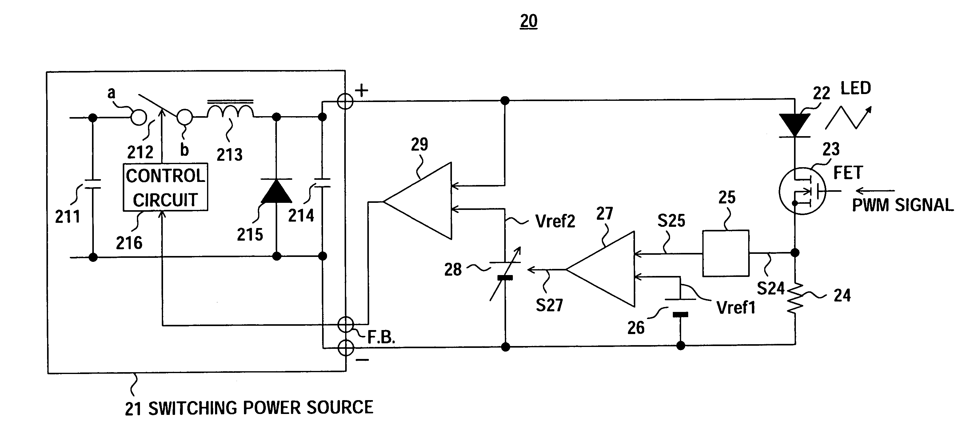
[0048]FIG. 5 is a circuit diagram of a light emitting element (LED) drive device according to a second embodiment of the present invention.

[0049]The LED drive device 20 of FIG. 5 is configured as a more specific version of the LED drive device of FIG. 4. Specifically, this is an embodiment using a boostdown chopper type switching power source (switching regulator) 21 as the constant voltage source, an n-channel insulating gate type field effect transistor (MOS-FET: hereinafter simply referred to as an “FET”) 23 as the switch circuit, a resistor 24 as the current detection unit, a peak hold circuit 25 as the sample and hold circuit, a constant current use reference voltage source 26 as the control unit (including the output voltage adjustment unit), a constant current control use error amplifier 27, a constant voltage use reference voltage source 28 having a function making the output voltage variable from the outside, and a constant voltage control use error amplifier 29.

[0050]The s...

third embodiment

[0068]FIG. 8 is a circuit diagram showing a light emitting element (LED) drive device according to a third embodiment of the present invention.

[0069]A LED drive device 20A of the present third embodiment is an example replacing the peak hold circuit 25, the constant current control use error amplifier 27, the constant current use reference voltage source 26, and the constant voltage use reference voltage source 28 of the second embodiment shown in FIG. 5 with a microcomputer 30. Further, in the third embodiment, the PWM signal is output from the same microcomputer.

[0070]In this case, the voltage detected by the current detection resistor 24 is input to the microcomputer 30. The microcomputer 30 converts the voltage from an analog to digital format at a not shown analog / digital converter, samples and holds it matching with the PWM signal generated by the microcomputer 30 per se, compares it with the current set value previously determined by software, converts the output in accordanc...


PUM

PropertyMeasurementUnit
resistanceaaaaaaaaaa
poweraaaaaaaaaa
poweraaaaaaaaaa

Abstract

A light emitting element drive circuit and a display system able to simultaneously perform constant current control and PWM control and able to perform a stable adjustment of luminance over a wide dynamic range, including a constant voltage source having an output voltage adjustment unit able to be changed in output voltage according to a signal from the outside, a switch circuit connected to the cathode side of the LED and ON / OFF controlled in accordance with a PWM signal from the outside, a current detection unit for detecting the current flowing in the circuit, and a sample and hold circuit for maintaining the current input value from the current detection unit for a constant period, and the output voltage adjustment unit receives as input the output of the sample and hold circuit, that is, the current value when the switch circuit is ON, and adjusts the output of the constant voltage source so that this value becomes a previously determined set value, to thereby make the current flowing in the LED constant.

Description

CROSS-REFERENCE TO RELATED APPLICATIONS[0001]The present invention contains subject matter related to Japanese Patent Application No. 2004-300015 filed in the Japan Patent Office on Oct. 14, 2004, and Japanese Patent Application No. 2005-228738 filed in the Japan Patent Office on Aug. 5, 2005, the entire contents of which being incorporated herein by reference.BACKGROUND OF THE INVENTION[0002]The present invention relates to a drive device for a light emitting diode (LED) or other light emitting element emitting light with a luminance in accordance with a flow of current and a display system having for example a non-light emitting transmission type display device using the same.[0003]The mainstream of backlights of liquid crystal panels is the cold cathode fluorescent lamp (CCFL) type using a fluorescent lamp, but a mercury-less type has been demanded for protection of the environment. Due to this, in recent years, LEDs have been looked at as promising light sources to take the plac...

Claims


Application Information

Patent Timeline
Patent Type & Authority Patents(United States)
IPC IPC(8): G09G3/36G02F1/13357H05B44/00H01L33/00H05B37/02
CPCG09G3/3406H05B33/0815H05B33/0818H05B33/0848G09G2320/0626G09G2320/0666Y02B20/347G09G2360/16H05B45/14Y02B20/30H05B45/375G09G3/32G02F1/133G09G3/20
Inventor OYAMA, YOSHIKI
Owner SATURN LICENSING LLC
Why Eureka
Try Eureka