Power amplifier linearization

Active Publication Date: 2007-12-25
HYPRES
View PDF8 Cites 64 Cited by
  • Summary
  • Abstract
  • Description
  • Claims
  • Application Information

AI Technical Summary

Benefits of technology

[0007]It is an object of this invention to perform corrections directly on the rf waveform for three major reasons: (1) near-perfect correction to even strong amplifier nonlineari

Problems solved by technology

In both communications and radar systems, the performance of the systems is limited by the linearity (or lack thereof) of the high power amplifiers used to transmit the RF output signals.
Nonlinearities in the response of the high power amplifiers create distortions that limit the dynamic range of the amplifiers.
Efforts to correct this problem, decrease the amplifier efficiency whi

Method used


Image

  • Power amplifier linearization
  • Power amplifier linearization
  • Power amplifier linearization

Examples


Embodiment Construction

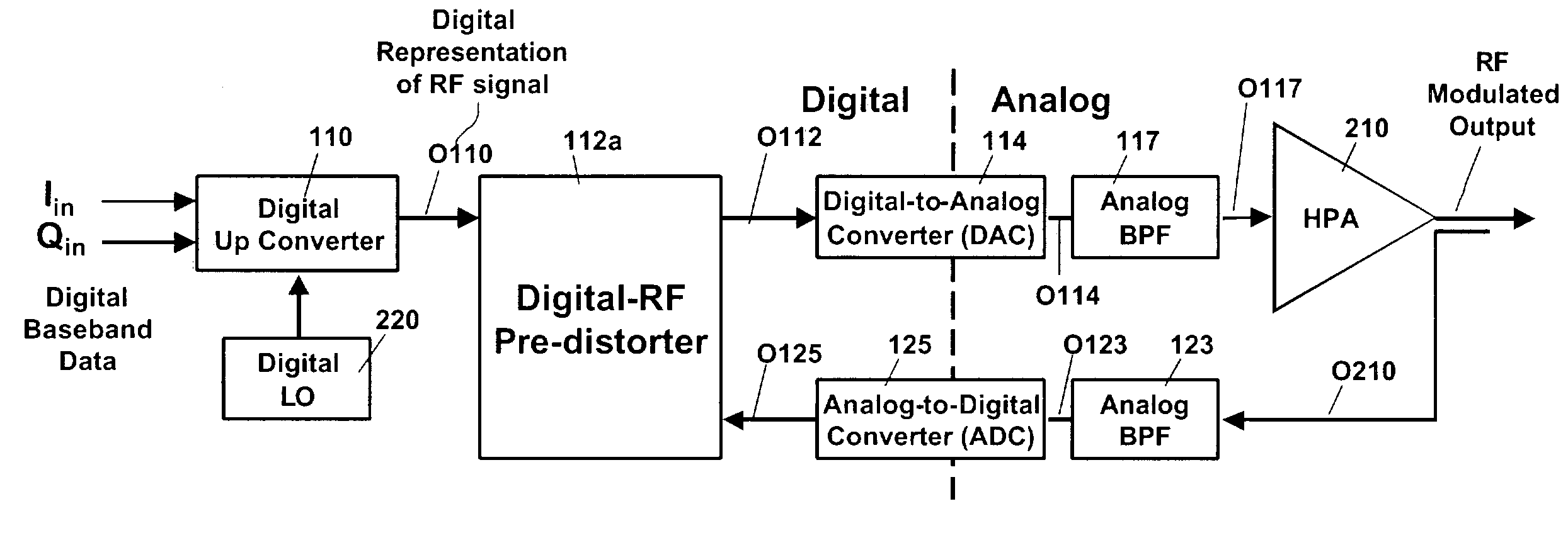
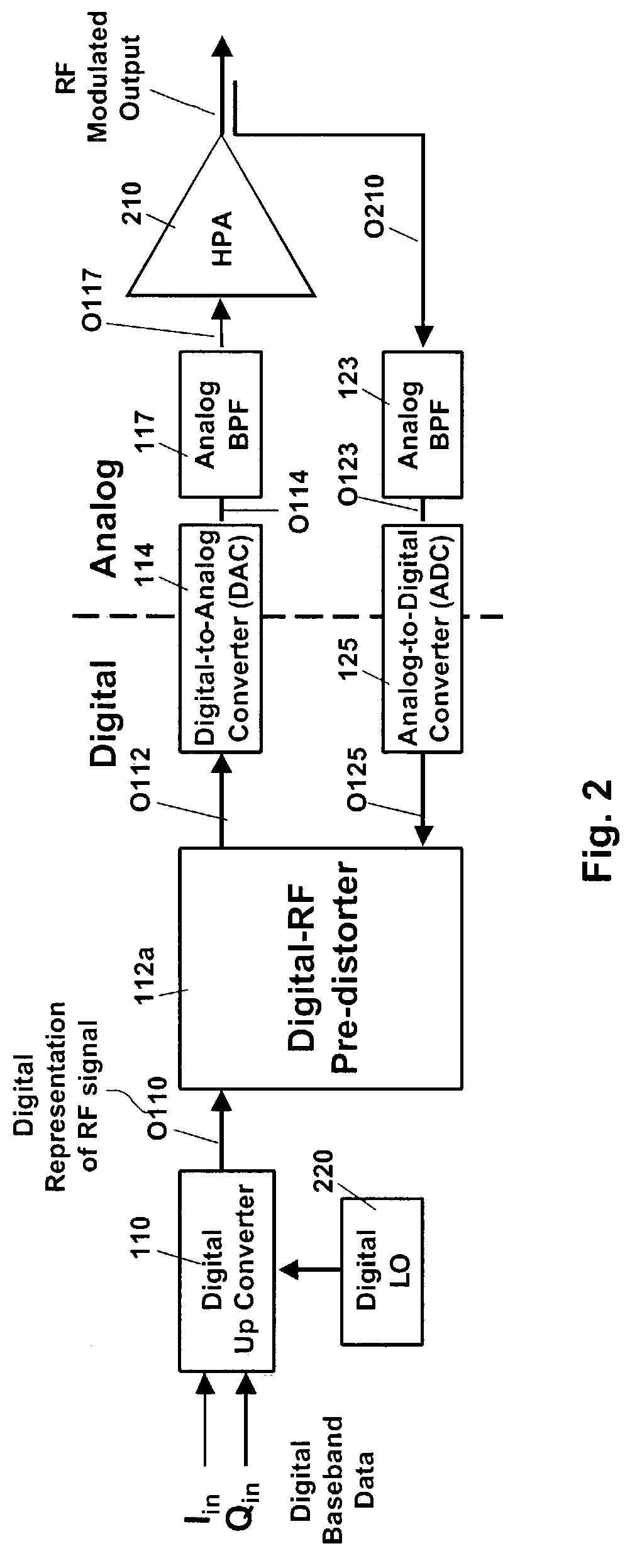
[0032]FIG. 2 is a general block diagram of a digital RF predistortion circuit embodying the invention. In accordance with the invention, digital baseband data signals (Iin and Qin) are supplied to a digital-up-converter (DUC) 110 which is modulated by a digital local oscillator 220. The output O110 of DUC 110 is a multi-bit RF modulated signal which is sampled at a very high rate (e.g., at more than 10 or 20 giga-samples per second, GSPS). The number of bits (for each signal sample) is normally selected to meet desired system requirements of precision and accuracy, with the precision and accuracy increasing with the number of bits. However, to handle a greater number of bits requires a corresponding increase in circuitry to handle the bits and this is often the limiting factor on the total number of bits (where the number of bits typically, but not necessarily, increase in binary fashion).

[0033]The RF modulated output O110 of up-converter 110 is fed to an input port of a digital RF ...


PUM


Abstract

A system for linearizing the output of a high power amplifier (HPA) designed to transmit an RF modulated signal includes in its transmit section a digital up-converter for processing baseband input signals and generating a desired digital RF waveform, T(s). The desired digital RF waveform T(s) is then fed to a digital predistorter circuit for producing a predistorted digital RF waveform P(s)T(s) which, as modified, may be applied via a high sampling speed high linearity digital to analog converter to the high power amplifier (HPA) to produce an output signal which is a linear function of the baseband input signal. The digital predistorter circuit may be of the adaptive type or of the predictive type. Circuits embodying the invention may include encoding circuitry for converting multi-bit signals to a serial stream of single-bit pulses for enabling simplification in the digital to analog conversion. In accordance with the invention, corrections for non-linearity of the HPA may be made directly on the RF waveform using ultra-high speed superconducting electronics (SCE) and decreasing the time delay between sensing a transmitted signal and generating a correcting (linearizing) signal.

Description

CROSS REFERENCE TO RELATED APPLICATIONS[0001]This application claims priority from provisional application Ser. No. 60 / 366,360 filed Mar. 21, 2002 for METHOD AND APPARATUS FOR ADAPTIVELY LINEARIZING A POWER AMPLIFIER by Deepnarayan Gupta and Oleg A. Mukhanov and provisional application Ser. No. 60 / 366,466 filed Mar. 21, 2002 for DYNAMIC DIGITAL RF-PREDISTORTER FOR PREDICTIVE LINEARIZATION OF HIGH POWER AMPLIFIERS by Deepnarayan Gupta the disclosure of which is incorporated herein by reference[0002]This invention was made with Government support under contract DSAG60-02-P-0281 awarded by the U.S. Army Space and Missile Defense Command. The Government has certain rights in the invention.BACKGROUND OF THE INVENTION[0003]This invention relates to apparatus and methods for linearizing the response of a high power amplifier (HPA).[0004]In both communications and radar systems, the performance of the systems is limited by the linearity (or lack thereof) of the high power amplifiers used to...

Claims


Application Information

Patent Timeline
IPC IPC(8): H04L25/49H04B15/00H03F1/32H04L27/36
CPCH03F1/3247H03F1/3294H04L27/368H04L27/367H03F2200/294H03F2200/372H03F2200/331
Inventor GUPTA, DEEPNARAYANMUKHANOV, OLEG A.
Owner HYPRES
Why Eureka
Try Eureka