Vacuum microelectronic acceleration transducer

An acceleration sensor and microelectronics technology, applied in the direction of acceleration measurement using inertial force, etc., can solve the problems of small capacitance test method complexity, high low-frequency noise, low sensitivity, etc., to improve long-term stability and temperature stability, signal processing circuit Simple, good temperature stability effect

Inactive Publication Date: 2006-04-12
CHONGQING UNIV
View PDF0 Cites 0 Cited by
  • Summary
  • Abstract
  • Description
  • Claims
  • Application Information

AI Technical Summary

Problems solved by technology

[0002] There are many types of acceleration sensors in the prior art, including acceleration sensors with various structures and principles such as force balance interdigital capacitive type, torsion capacitive type, cantilever beam capacitive type, tunnel breakdown type, piezoresistive type, piezoelectric type, etc. , the characteristics of the piezoresistive acceleration sensor are: simple processing technology, good linearity, but serious temperature effect, unstable working state, and low sensitivity; the characteristics of the capacitive acceleration sensor are: small temperature effect, relatively high sensitivity, low noise Good characteristics, low drift, low power consumption, but the small capacitance test method is complex, affected by distributed capacitance and electromagnetic interference; the characteristics of the tunnel acceleration sensor are: high sensitivity, current detection, strong anti-interference ability, small temperature effect, High linearity, but difficult processing, low yield and high low-frequency noise
It is difficult for the above various acceleration sensors to meet the requirements of radiation resistance, high sensitivity, and high resolution at the same time.

Method used


Image

  • Vacuum microelectronic acceleration transducer
  • Vacuum microelectronic acceleration transducer
  • Vacuum microelectronic acceleration transducer

Examples


Embodiment Construction

[0020] Below in conjunction with accompanying drawing the technical scheme of the present invention is further described:

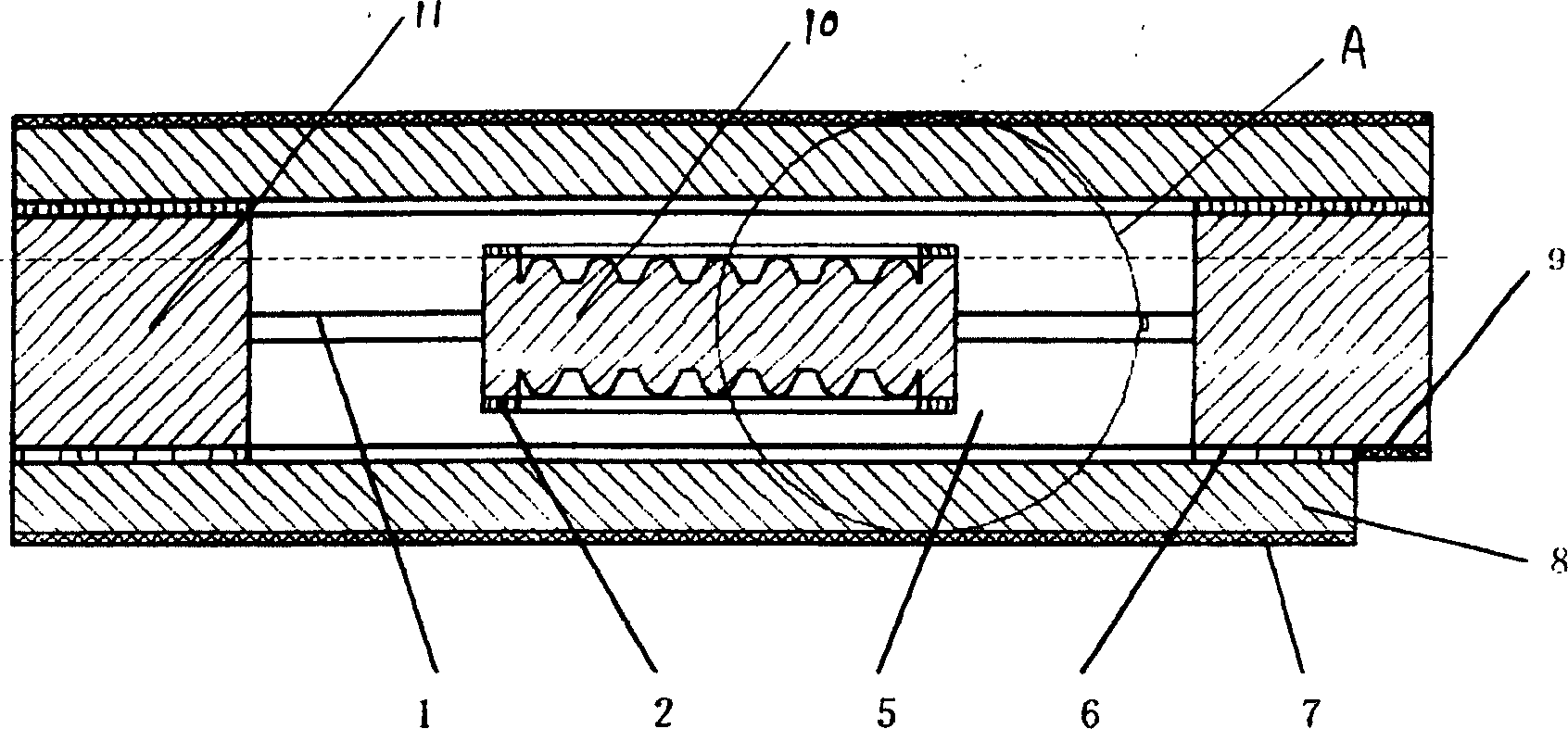
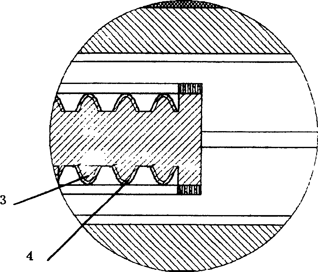
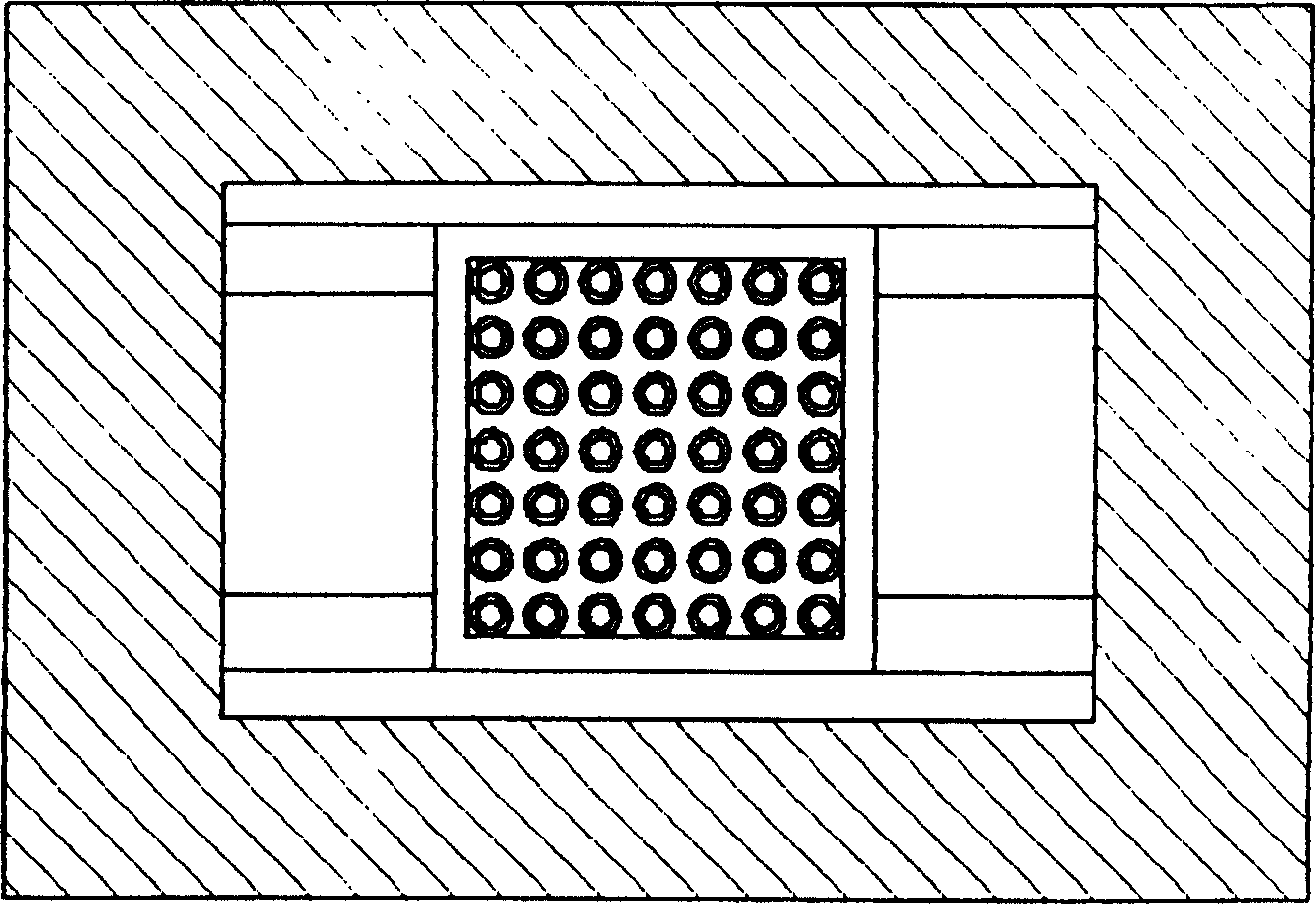
[0021] In the figure, 1 is the cantilever beam of the moving plate, 2 is the overload protection ring, 3 is the silicon micro-field emission cathode cone array on the upper and lower sides of the mass block, 4 is the diamond film, 5 is the vacuum microcavity, and 6 is the insulating layer , 7 is an anode plate output electrode, 8 is an anode plate, 9 is a moving plate output electrode, 10 is a mass block, 11 is a substrate, 12 is an I-V conversion circuit, 13 is a differential circuit, and 14 is a signal filter amplifier circuit.

[0022] see figure 1 , figure 2 , image 3 and Figure 4 , The integrated vacuum microelectronic acceleration sensor mainly includes a moving plate, an insulating layer 6, a vacuum microcavity 5, two upper and lower anode plates 8 and a signal detection circuit. The moving plate is hollow, and is bonded with the upper and l...


PUM


Abstract

The invention is a vacuum microelectronic acceleration sensor, including active polar plate, insulating layer, vacuum microcavity, top and bottom anode plates and signal detecting circuit. The active polar plate is hollow, the top and bottom anode plates interlink with the active polar plate to form a vacuum cavity in the middle. Where the active polar plate has basal plate which supports a mass block in the middle by cantilever beam, the top and bottom surface of the mass block are distributed with silicon micro field emission cathode cone array and overload protective rings, there is output electrode of the active polar plate on the basal plate, there is another output electrode on the anode plate. The above electrodes are connected with the signal detecting circuit by lines. Its advantages of radioresistance, good temperature stability, fast response, high sensitivity, high resolution, etc, and has extremely wide use.

Description

technical field [0001] The invention belongs to the technical field of acceleration sensors, in particular to an integrated vacuum microelectronic acceleration sensor and a manufacturing method thereof. Background technique [0002] There are many types of acceleration sensors in the prior art, including acceleration sensors with various structures and principles such as force balance interdigital capacitive type, torsion capacitive type, cantilever beam capacitive type, tunnel breakdown type, piezoresistive type, piezoelectric type, etc. , the characteristics of the piezoresistive acceleration sensor are: simple processing technology, good linearity, but serious temperature effect, unstable working state, and low sensitivity; the characteristics of the capacitive acceleration sensor are: small temperature effect, relatively high sensitivity, low noise Good characteristics, low drift, low power consumption, but the small capacitance test method is complex, affected by distri...

Claims


Application Information

Patent Timeline
Patent Type & Authority Patents(China)
IPC IPC(8): G01P15/12
Inventor 温志渝温中泉
Owner CHONGQING UNIV
Why Eureka
Try Eureka