Wireless integrated automatic exposure control module

Inactive Publication Date: 2007-12-25
GENERAL ELECTRIC CO
View PDF3 Cites 25 Cited by
  • Summary
  • Abstract
  • Description
  • Claims
  • Application Information

AI Technical Summary

Problems solved by technology

The temporal response of the ion chamber design does not account for limitations in the exposure control system.
Yet another drawback with conventional automatic exposure control is when ion chamber characteristics are embedded in the system level AEC design, then changing ion chamber designs or suppliers requires a new software release to incorporate any differences in performance.

Method used


Image

  • Wireless integrated automatic exposure control module
  • Wireless integrated automatic exposure control module
  • Wireless integrated automatic exposure control module

Examples


an embodiment

Methods of an Embodiment

[0048]In the previous section, a system level overview of the operation of an embodiment was described. In this section, the particular methods performed by the smart ion chamber of such an embodiment are described by reference to a series of flowcharts. Describing the methods by reference to a flowchart enables one skilled in the art to develop such programs, firmware, or hardware, including such instructions to carry out the methods on suitable processing device such as the processor of the clients executing the instructions from computer-readable media. Similarly, the methods performed by the server computer programs, firmware, or hardware are also composed of computer-executable instructions. Method 600 is performed by a client program executing on, or performed by firmware or hardware that is a part of, a computing device and is inclusive of the acts required to be taken by an aptly programmed computer.

[0049]FIG. 6 is a flowchart of method performed by a...


PUM


Abstract

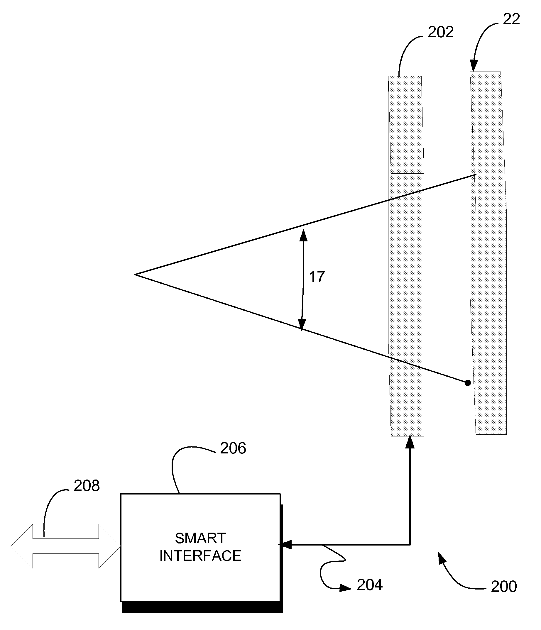
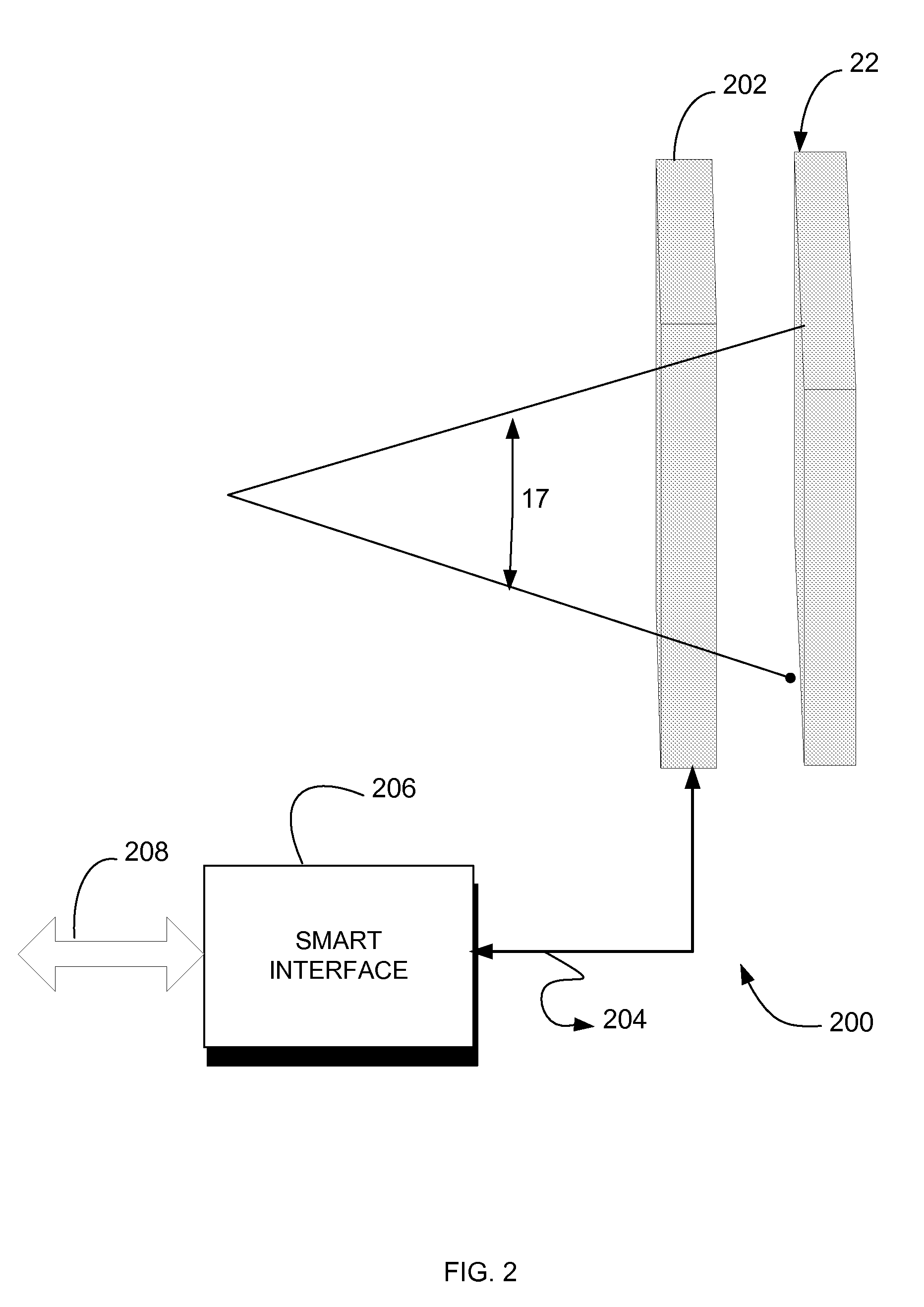
Systems and methods for providing independent exposure detection, X-ray spectrum and timing compensation, and providing an exposure termination signal to an X-ray system. The system incorporates an interface for receiving exposure characteristic data such as kVp, spectral filter, and focal spot. The system through a programmed controller determines one or more control parameters based on the received exposure characteristic data and generates a control signal for controlling an X-ray source.

Description

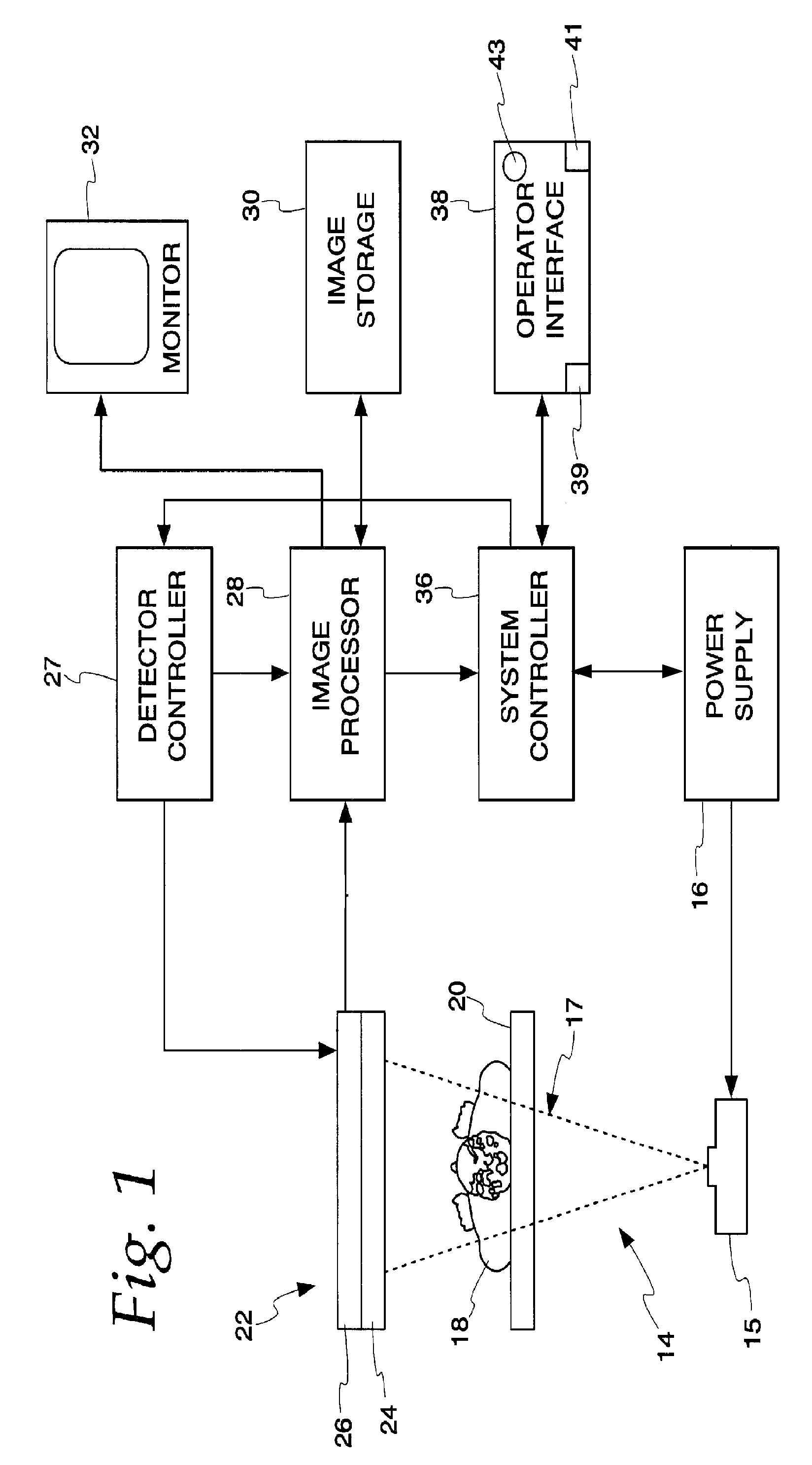
FIELD OF THE INVENTION[0001]The field of the invention is X-ray imaging systems, and particularly, automatic exposure control and exposure optimization for X-ray systems through a wireless integrated automatic exposure control module.BACKGROUND OF THE INVENTION[0002]Automatic exposure control (AEC) is used in X-ray imaging equipment to control the exposure per image. The goal is to maintain image quality while minimizing patient exposure. The AEC develops a signal proportional to the X-ray flux into the image receptor. This signal is used to regulate the total exposure for each image either by terminating the exposure or by adjusting the X-ray flux rate. In this usage, the X-ray technique (kVp, spectral filter, focal spot, etc) is prescribed by the operator. Often these are preset and selected based on patient size and anatomy to be imaged. Thus, the role of the AEC is to regulate the correct total exposure.[0003]Generally, an incident radiation dose must be adjusted for each object...

Claims


Application Information

Patent Timeline
Patent Type & Authority Patents(United States)
IPC IPC(8): H05G1/42
CPCA61B6/544A61B6/00
Inventor SAUNDERS, ROWLAND F.
Owner GENERAL ELECTRIC CO
Why Eureka
Try Eureka