
Exhaust gas purification system of internal combustion engine

a technology of exhaust gas purification system and internal combustion engine, which is applied in the direction of exhaust treatment electric control, electrical control, separation process, etc., can solve the problems of deterioration in fuel cost accompanies the above temperature-increasing means, rapid increase of dpf temperature, and rapid combustion of particulate matter, so as to reduce the flow rate of exhaust gas, inhibit the deterioration of fuel cost, and improve the effect of temperature-in

Inactive Publication Date: 2008-01-01
DENSO CORP
View PDF17 Cites 36 Cited by
  • Summary
  • Abstract
  • Description
  • Claims
  • Application Information

AI Technical Summary

Benefits of technology

The present invention relates to an exhaust gas purification system for an internal combustion engine that includes a particulate filter. The system includes a deposition quantity estimating means, temperature increasing means, and regeneration controlling means. The regeneration controlling means determines when to start and stop the regeneration of the particulate filter based on the amount of particulate matters deposited on it. The temperature increasing means increases the temperature of the particulate filter to target temperature. The exhaust gas flow rate controlling means changes the intake air quantity to maintain the temperature of the particulate filter near the target temperature and inhibit deviation from it due to changes in the flow rate of exhaust gas. This improves the temperature-increasing performance and prevents deterioration in fuel cost while ensuring safety during regeneration.

Problems solved by technology

However, deterioration in a fuel cost accompanies the above temperature-increasing means.
However, the particulate matters are combusted rapidly and the DPF temperature increases rapidly if the DPF temperature is too high as shown in FIG. 21.
In the case where the particulate matters are combusted rapidly and the DPF temperature Tdpf increases rapidly, there is a possibility that the DPF is damaged or an oxidation catalyst supported by the DPF is degraded.
However, if the temperature control is performed to conform the EGR ratio to the target value during the regeneration of the DPF, optimum temperature-increasing performance cannot be obtained.
In such a case, a heat amount released from the DPF to the exhaust gas increases and the deterioration in the fuel cost necessary to increase the temperature becomes problematic.
As a result, control accuracy is deteriorated.
In such a case, there is a possibility that the DPF is damaged by the rapid combustion of the particulate matters.
Accordingly, it takes a long time to sense and to correct the variation.
Therefore, it is difficult to design a fast-response control system and to quickly correct influences of the temperature variation.
However, this method cannot be used during a regeneration period, in which the regeneration is performed.
Therefore, the variation in the exhaust gas flow rate cannot be inhibited as shown by broken lines in FIG. 22, and the temperature variation cannot be inhibited.

Method used


Image

  • Exhaust gas purification system of internal combustion engine
  • Exhaust gas purification system of internal combustion engine
  • Exhaust gas purification system of internal combustion engine

Examples


Embodiment Construction

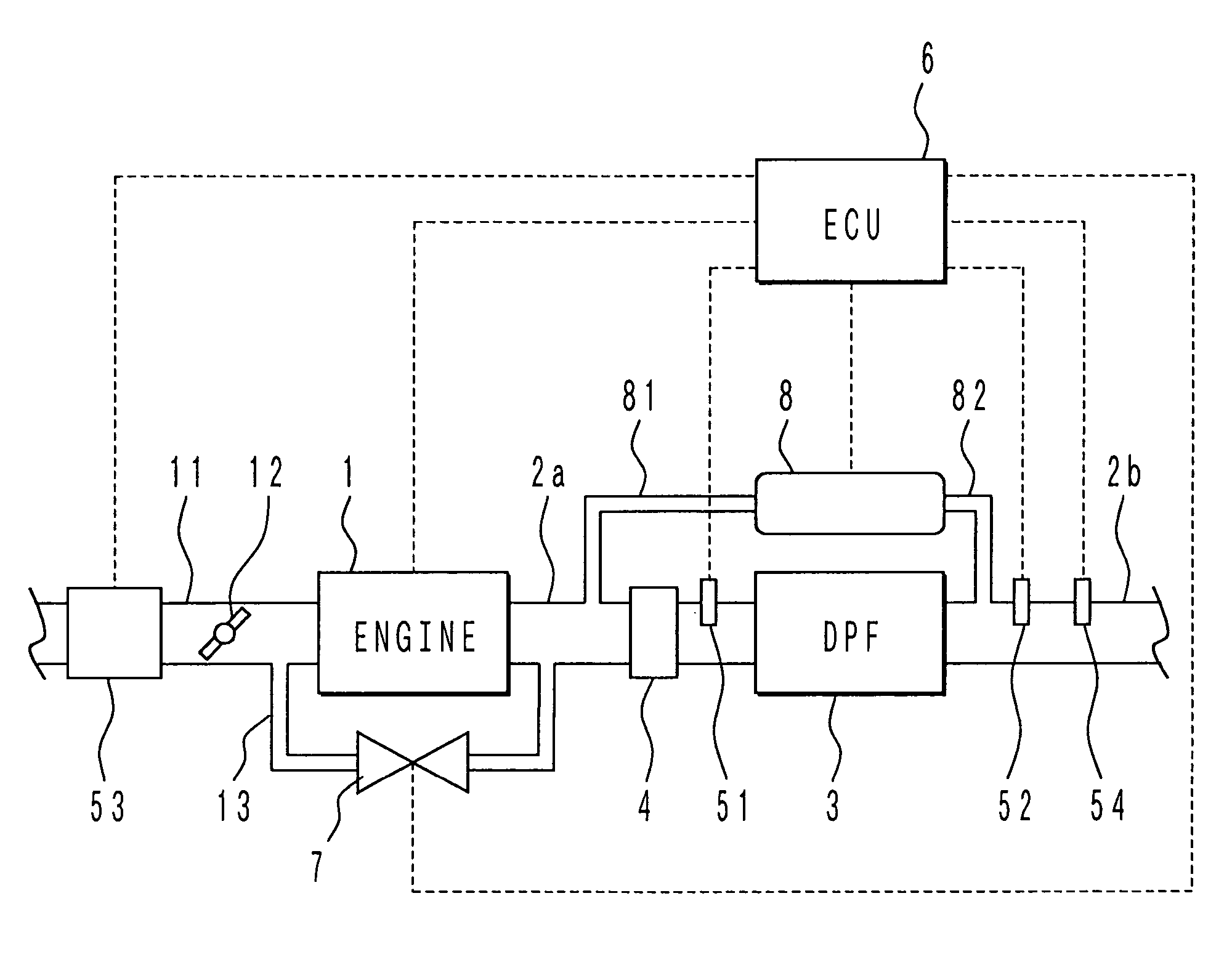
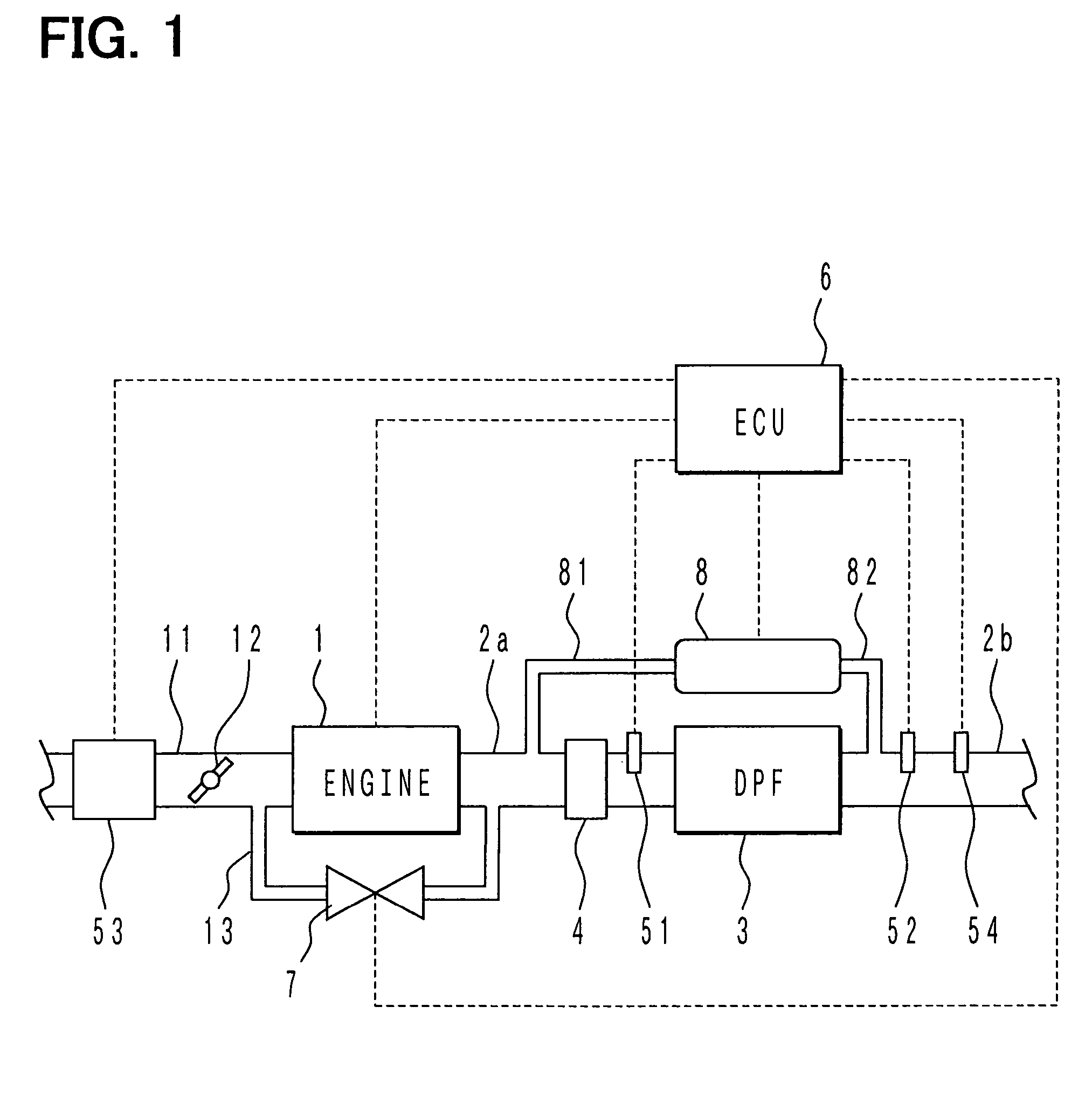
[0046]Referring to FIG. 1, an exhaust gas purification system of a diesel engine 1 according to an embodiment of the present invention is illustrated.

[0047]A diesel particulate filter (DPF) 3 is disposed between exhaust pipes 2a, 2b, which constitute an exhaust passage 2 of the diesel engine 1. A diesel oxidation catalyst (DOC) 4 is disposed in the exhaust pipe 2a upstream of the DPF 3. The DPF 3 is a ceramic filter having a publicly known structure. For instance, the DPF 3 is made of heat-resistant ceramics such as cordierite and is formed in the shape of a honeycomb structure. An end of each one of multiple cells of the honeycomb structure as gas passages is blocked alternately on an inlet side or on an outlet side of the honeycomb structure. Exhaust gas discharged from the engine 1 flows downstream while passing through porous partition walls of the DPF 3. Meanwhile, particulate matters contained in the exhaust gas are collected in the DPF 3 and gradually deposited in the DPF 3.

[...


PUM

PropertyMeasurementUnit
temperatureaaaaaaaaaa

Abstract

An oxidation catalyst is disposed upstream of a diesel particulate filter (DPF) in an exhaust passage of a diesel engine. An electronic control unit (ECU) operates temperature increasing circuit to combust and eliminate particulate matters deposited on the DPF. The ECU determines execution and stoppage of regeneration of the DPF based on a quantity of the particulate matters deposited on the DPF. The ECU increases an exhaust gas recirculation quantity (EGR quantity) during the regeneration to reduce an intake air quantity from the intake air quantity in a non-regeneration period and to achieve a flow rate of the exhaust gas passing through the DPF suitable for the temperature increase. The ECU corrects a valve opening degree of an EGR control valve based on the sensed intake air quantity to reduce a variation in the exhaust gas flow rate.

Description

CROSS REFERENCE TO RELATED APPLICATION[0001]This application is based on and incorporates herein by reference Japanese Patent Application No. 2004-72911 filed on Mar. 15, 2004.BACKGROUND OF THE INVENTION[0002]1. Field of the Invention[0003]The present invention relates to an exhaust gas purification system of an internal combustion engine having a particulate filter in an exhaust passage. Specifically, the present invention relates to temperature increasing control of a particulate filter during regeneration of the particulate filter.[0004]2. Description of Related Art[0005]A known exhaust gas purification system of a diesel engine includes a particulate filter (a diesel particulate filter, DPF) for collecting particulate matters (PM) discharged from the engine. The system increases temperature of the DPF, for instance, over 600° C., when a quantity of the particulate matters deposited on the DPF (a PM deposition quantity) reaches a predetermined value. Thus, the particulate matters...

Claims


Application Information

Patent Timeline
Patent Type & Authority Patents(United States)
IPC IPC(8): F01N3/00F02M25/07B01D46/42B01D53/94F01N3/02F01N3/023F01N3/025F01N3/035F01N3/08F01N9/00F01N11/00F02D9/02F02D21/08F02D41/02F02D41/04F02D41/38F02D45/00
CPCF02D41/029F01N2250/02F01N2250/06F01N2260/04F01N2430/06F02D41/0055F02D2041/0017
Inventor OKUGAWA, SHINICHIROKOBAYASHI, KAZUOHARAGUCHI, HIROSHI
Owner DENSO CORP
Learn More