Miniature manipulator for servicing the interior of nuclear steam generator tubes

a technology for manipulators and generator tubes, applied in the field of robot systems, can solve the problems of contaminating steam, degrading of some tubes, and generally not being able to replace degraded tubing,

Active Publication Date: 2008-01-01
WESTINGHOUSE ELECTRIC CORP
View PDF59 Cites 30 Cited by
  • Summary
  • Abstract
  • Description
  • Claims
  • Application Information

AI Technical Summary

Benefits of technology

[0013]This invention meets the foregoing objectives by providing a simple, relatively small steam generator manipulator that employs a combination of pneumatics, hydraulics and a single motorized axis. The manipulator is made up of three basic components; a base member, a block member, and a foot member. The base member has at least one, and preferably two, grippers for releasably gripping a tube extending through a tube sheet. The base member also supports an end effector, i.e., a tool or inspection device, for performing the desired service operation. The block member is connected to the base member in a manner that provides linear movement and rotation relative to the base member. The foot member is connected to the block member in a manner that provides linear movement relative to the block member. The foot member also has at least one, and preferably two, grippers for releasably gripping a tube extending through the tube sheet. The block member has two directions of linear travel between the block member and the base member, preferably in the horizontal and vertical directions. In the preferred embodiment, the grippers exert a force in a direction to draw the member associated with at least one of the grippers toward the tube sheet where limit pins maintain the member a predetermined distance from the tube sheet. With the limit pins tightly against the tube sheet, the manipulator is forced to stay parallel and in close proximity to the tube sheet. The grippers are preferably pneumatically operated and are provided with a spring-bias in a gripping position so that the manipulator does not lose support upon the loss of compressed air feed. In the preferred embodiment, the manipulator assembly is approximately 30 lbs. or less with the ability to support approximately a 70 lb. payload, i.e., end effector.

Problems solved by technology

Occasionally during the operation of the steam generator, degradation occurs in some of the tubes.
This is undesirable because the primary coolant is radioactive and any leakage of the reactor coolant into the secondary side of the generator contaminates the steam.
It is generally not practical, however, to replace degraded tubing, but instead the steam generator is periodically inspected and the effected tubes are plugged at both ends.
By contrast, limited movement arms generally are capable of moving an end effector only along a selected two-dimensional trajectory, and cannot maintain the end effector at a desired orientation along this trajectory.
Unfortunately, neither of these types of robotic arm is without drawbacks.
This is a significant shortcoming as every such installation procedure is not only laborious and time-consuming, but also results in the exposure of the operating personnel to potentially harmful radiation.
This last drawback is of growing importance, as the NRC has placed greater limitations upon the amount of radiation exposure that such operating personnel may absorb.
Moreover, the fact that such limited movement robotic arms can not maintain an end effector at a desired orientation while simultaneously moving it across a chosen trajectory across the tube sheet renders them useless for end effectors that require a constant orientation, such as weld heads.
However, prior art full movement robotic arms such as ROSA also have limitations that offer room for improvement.
Specifically, the Applicants have noticed that a vertically oriented “elbow” of the ROSA disadvantageously limits the number and length of the possible trajectories that the distal end of the arm may make without mechanically interfering with the bowl-like wall of the channel head, or the divider plate within the channel head, or the cables which vertically drape down from end effectors such as the eddy current probes used to inspect and determine the condition of the interior walls of the heat exchanger tubes.
Applicants have also observed that the prior art ROSA is configured so that a large portion of the arm is cantileverly supported from its vertically oriented elbow, which in turn applies a significant amount of life-reducing extraneous torque to the electric motor driving the joint, and reduces its payload carrying capability.
Further, Applicants have observed that the motion of the distal end of such robotic arms is not smooth enough to conduct certain weld operations.
In the past, much of the older steam generator tubing became degraded and required significant plugging, sleeving, or total steam generator replacement.
Current steam generator manipulators are generally heavy (greater than 100 lbs.) and sophisticated, which adds time and personnel radiation exposure to transport, set up, and install in the steam generators.
Current manipulators are also too large in size to install multiple manipulators in either section of most steam generator channel heads.
Use of a single manipulator to position more than two eddy current probes simultaneously has not been very successful because failure of one probe will generally result in the same number of robotic moves as if one or two probes were used.
The control system along with the complexity of the manipulator are generally expensive to purchase and maintain.
In addition, position adjustment and verification is usually required due to the varied deflection of the manipulator under load coupled with inaccuracy of the robot.

Method used


Image

  • Miniature manipulator for servicing the interior of nuclear steam generator tubes
  • Miniature manipulator for servicing the interior of nuclear steam generator tubes
  • Miniature manipulator for servicing the interior of nuclear steam generator tubes

Examples


Embodiment Construction

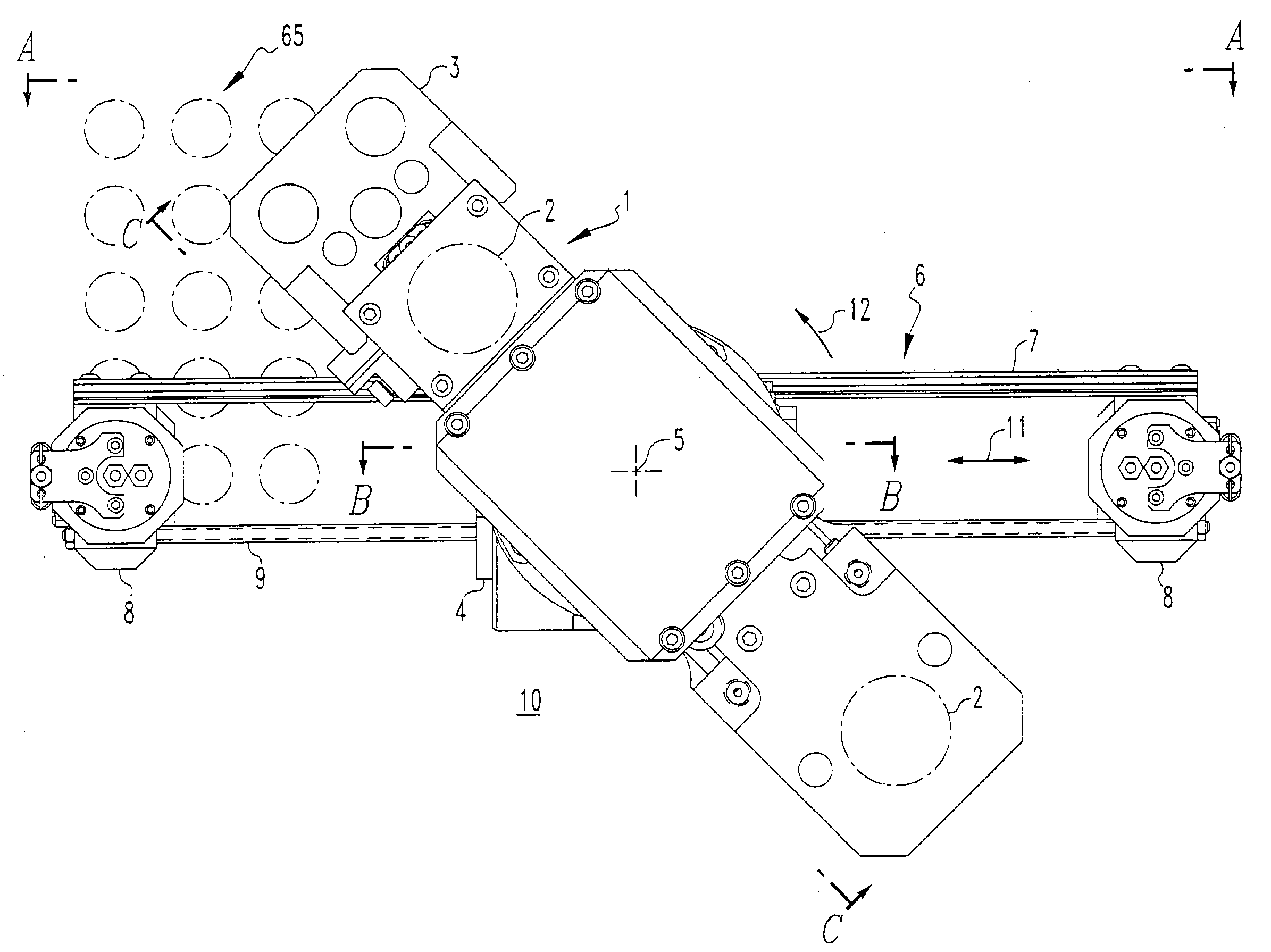
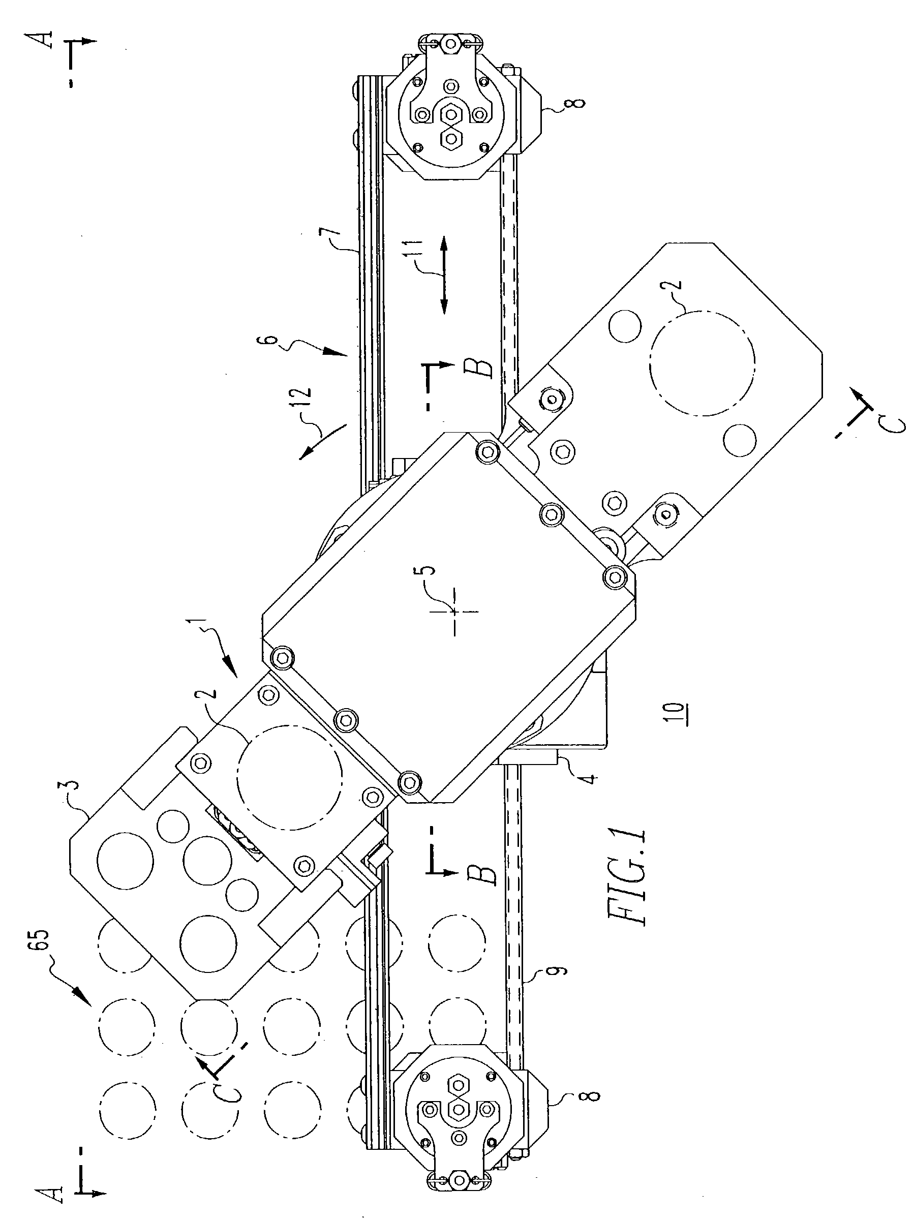
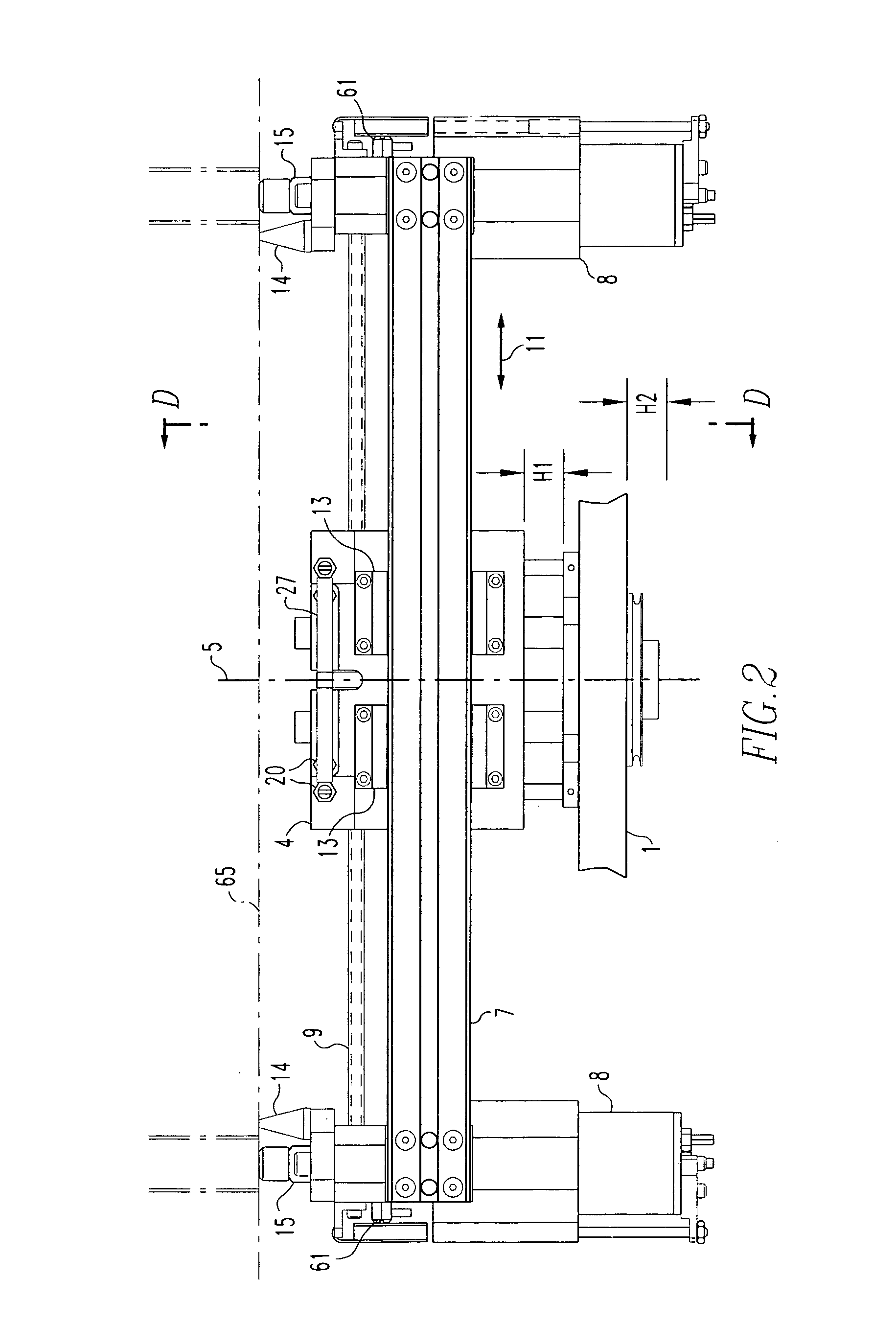
[0028]FIG. 1 shows the manipulator 10 of this invention mounted to a tube sheet 65 of a nuclear steam generator. The invention supports itself using two sets of expandable and translatable grippers 8 and 2 that anchor into the steam generator tube ends. There are three major components that comprise the invention. The first major component, the base member 1, contains a set of grippers 2, solenoids 38 (that will be described hereafter with regard to FIGS. 7 and 9) to operate the manipulator and a rotation mechanism 64 (that will be described hereafter with regard to FIG. 8) and serves as a framework for attachment of cabling and end effectors. A guide block 3 for eddy current inspection is shown attached to the base 1. The end effectors attach to the guide block as will be described hereafter The second major component is the cylinder block 4. The cylinder block contains a linear drive motor and can rotate with respect to the base member 1 about axis 5. As is described in more detai...


PUM


Abstract

A manipulator for servicing tubes extending through a tube sheet having three major components: a base member, a block member, and a foot member. The base member has a holder for supporting tooling or inspection devices. The base member also has at least one gripper for releasably gripping a tube extending through the tube sheet. The block member is connected to the base member for linear movement and rotation relative to the base member. The foot member is connected to the block member for linear movement relative to the block member. The foot member has at least one, and preferably two grippers, for releasably gripping a tube extending through the tube sheet. The manipulator supports itself using the two sets of expandable and translatable grippers that anchor into the tube ends and can move from tube to tube by alternately engaging each set of grippers.

Description

CROSS-REFERENCE TO RELATED APPLICATION[0001]The present application is a traditional application based on U.S. Provisional Application Ser. No. 60 / 398,000, filed Jul. 22, 2002.BACKGROUND OF THE INVENTION[0002]1. Field of the Invention[0003]This invention generally concerns robotic systems and is specifically concerned with an improved robotic light-weight system for servicing the heat exchanger tubes of a nuclear steam generator.[0004]2. Related Art[0005]In a pressurized water nuclear powered electric generating system, the heat generated by the nuclear reaction is absorbed by a primary coolant that circulates through the reactor core and is utilized to generate steam in a steam generator. The steam generator typically is an upright cylindrical pressure vessel with hemispherical end sections. A traverse plate called a tube sheet, located at the lower end of the cylindrical section, divides the steam generator into a primary side, which is the lower hemispherical section below the tu...

Claims


Application Information

Patent Timeline
Patent Type & Authority Patents(United States)
IPC IPC(8): F22B37/00F28F11/00
CPCF22B37/006F28F11/00G21C17/017Y10S165/003Y02E30/00Y02E30/30G21D1/02G21D9/00
Inventor HAWKINS, PHILLIP J.PETROSKY, LYMAN J.
Owner WESTINGHOUSE ELECTRIC CORP
Why Eureka
Try Eureka