Honeycomb structure

a honeycomb and structure technology, applied in the field of honeycomb structure, can solve the problems of cracks at corner parts, serious problems, contaminants harmful to the environment and the human body, etc., and achieve the effect of low pressure loss

Active Publication Date: 2008-01-08
IBIDEN CO LTD
View PDF80 Cites 52 Cited by
  • Summary
  • Abstract
  • Description
  • Claims
  • Application Information

AI Technical Summary

Benefits of technology

[0022]The present invention has been devised so as to solve the above-mentioned problems, and its object is to provide a honeycomb structural body (filter) which has a low pressure loss upon collecting particulates, makes it possible to deposit a great amount of particulates and ashes, and is less likely to generate cracks.
[0023]In order to achieve the above-mentioned object, the present inventors have studied hard, and consequently found that, in the case of through holes located at corner portions (four corners) of each of columnar ceramic members of an aggregate-type filter, since the number of adjacent through holes is smaller in comparison with those through holes located at the other portions, the flow rate of exhaust gas flowing though the holes becomes lower, and that for this reason, at the above-mentioned corner portions (four corners), there is a delay in a temperature rise upon burning particulates to cause a concentrated thermal stress and the subsequent cracks; thus, the present invention has been completed.
[0024]In other words, the columnar honeycomb structural body of the present invention includes a plurality of through holes placed in parallel with one another in the length direction; and wall portion that separates the plurality of through holes from one another and constitutes circumferential face, wherein the above-mentioned plurality of throughholes comprises: a group of large-capacity through holes, with one end thereof being sealed so as to cause the total of areas of cross-section perpendicular to the length direction to become relatively greater; and a group of small-capacity through holes, with the other end thereof being sealed so as to cause the total of areas of the above-mentioned cross-section to become relatively smaller, the above-mentioned circumferential face of the above-mentioned columnar honeycomb structural body having a chamfered corner portion.

Problems solved by technology

In recent years, particulates such as soot, contained in exhaust gases that are discharged from internal combustion engines of vehicles such as buses and trucks and construction equipment, have raised serious problems as contaminants harmful to the environment and the human body.
However, in the case where the integrated filter is formed into a column shape, cracks tend to occur at corner portions (four corners) due to a thermal stress imposed thereon upon burning particulates.
In the same manner, at corner portions (four corners) of columnar ceramic members forming an aggregate-type filter, cracks also tend to occur due to a thermal stress imposed thereon upon burning particulates.

Method used


Image

  • Honeycomb structure
  • Honeycomb structure
  • Honeycomb structure

Examples


example 1

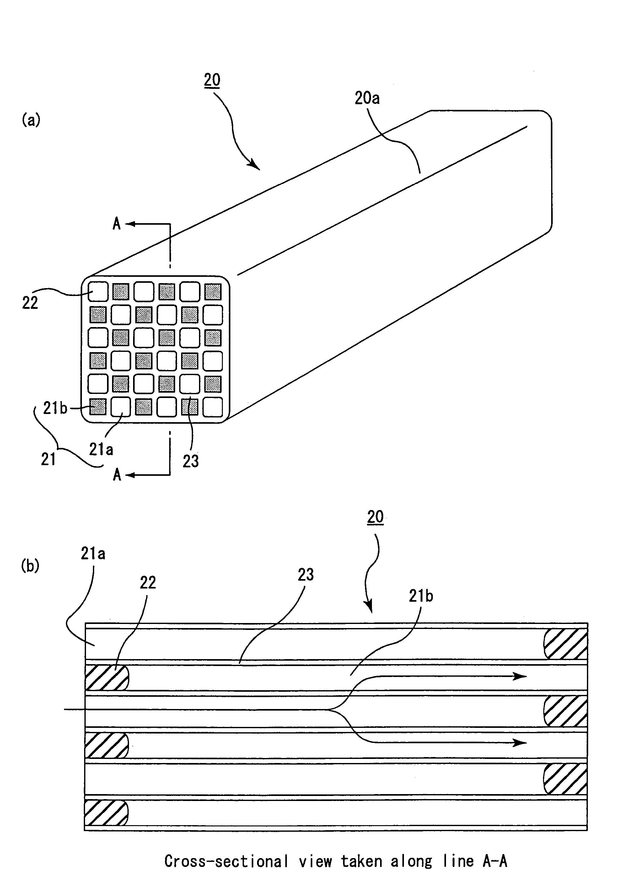
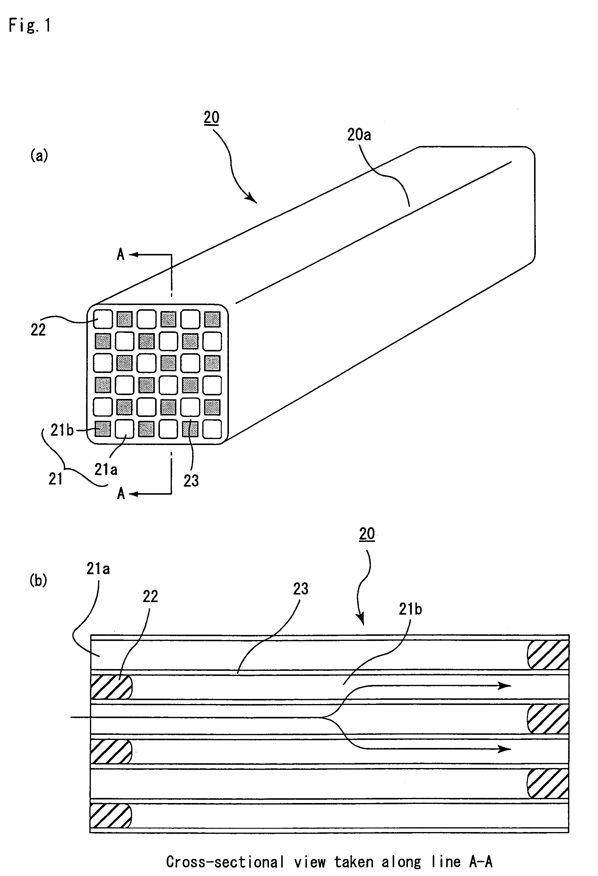
[0182](1) Powder of α-type silicon carbide having an average particle size of 10 μ(60% by weight) and powder of β-type silicon carbide having an average particle size of 0.5 μm (40% by weight) were wet-mixed, and to 100parts by weight of the resulting mixture were added and kneaded 5 parts by weight of an organic binder (methyl cellulose) and 10 parts by weight of water to obtain a mixed composition. Next, after a slight amount of a plasticizer and a lubricant have been added and kneaded therein, the resulting mixture was extrusion-molded so that a square columnar raw molded body, which had approximately the same cross-sectional shape as the cross-sectional shape shown in FIG. 5(b) and R-chamfered faces with an R-dimension of 0.3 mm on corner portions on the circumferential face, with four through holes located at the four corners being large-capacity through holes 21a, was manufactured.

[0183]Next, the above-mentioned raw molded body was dried by using a micro-wave drier or the like...

examples 2 to 4

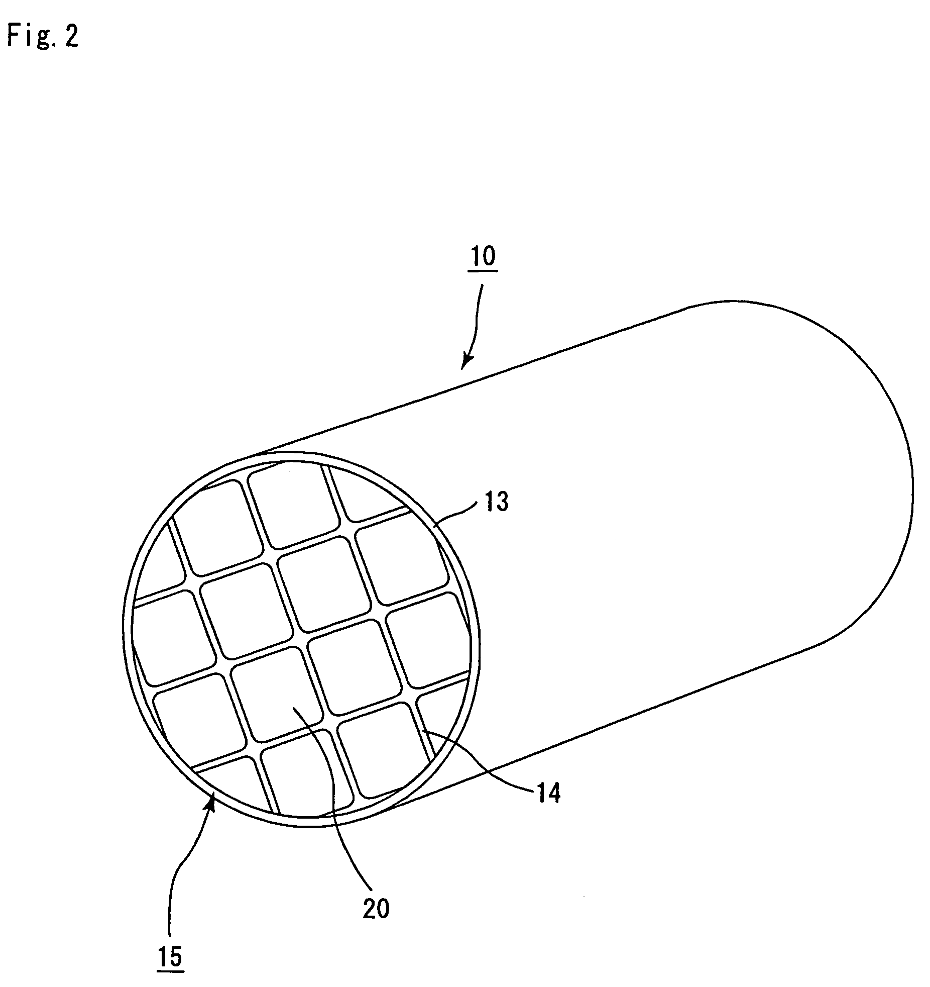
[0189]The same processes as Example 1 were carried out except that the R-dimension of R-chamfered faces formed on corner portions of the circumferential face of each of the integrated honeycomb structural bodies 20 was set to 0.4 mm (Example 2), 0.6 mm (Example 3) and 0.8 mm (Example 4) respectively so that the aggregate-type honeycomb structural body 10 was manufactured.

examples 5 to 8

[0190]The same processes as Examples 1 to 4 were carried out except that the extrusion-molding process was carried out by changing a die so that a raw molded body having a square column shape, which had more through holes by one row in each of longitudinal and lateral rows, with four through holes located at the four corners being constituted by two large-capacity through holes 21a and two small-capacity through holes 21b, was manufactured and that a sealing material paste was injected so that each of the large-capacity through holes 21a was sealed at the end face on the outlet side with each of the small-capacity through holes 21b being sealed at the end face on the inlet side; thus, an aggregate-type honeycomb structural body 10 was manufactured.

[0191]Here, the R-dimension of R-chamfered faces formed on corner portions of the circumferential face of each of the integrated honeycomb structural bodies 20 was set to 0.3 mm (Example 5), 0.4 mm (Example 6), 0.6 mm (Example 7) and 0.8 m...


PUM

PropertyMeasurementUnit
porosityaaaaaaaaaa
porosityaaaaaaaaaa
porosityaaaaaaaaaa

Abstract

An object of the present invention is to provide a honeycomb structural body (filter) which has a low pressure loss upon collecting particulates, makes it possible to deposit a great amount of particulates and ashes, and is less likely to produce cracks. The columnar honeycomb structural body of the present invention includes a plurality of through holes placed in parallel with one another in the length direction, and wall portion that separates the plurality of through holes from one another and constitutes a circumferential face, wherein the plurality of through holes are composed of a group of large-capacity through holes, with one end thereof being sealed so as to cause the total of areas of cross-section perpendicular to the length direction to become relatively greater, and a group of small-capacity through holes, with the other end thereof being sealed so as to cause the total of areas of the above-mentioned cross-section to become relatively smaller, and the above-mentioned circumferential face of the columnar honeycomb structural body has a chamfered corner portion.

Description

CROSS REFERENCE TO RELATED APPLICATION[0001]This application claims benefit of priority to Japanese Patent application Nos. 2002-267819filed on Sep. 13, 2002, 2003-57631 filed on Mar. 4, 2003, and 2003-178712 filed on Jun. 23, 2003, the contents of which are incorporated by reference herein.TECHNICAL FIELD[0002]The present invention relates to a honeycomb structural body used as a filter or the like for removing particulates and the like contained in exhaust gases discharged from an internal combustion engine such as a diesel engine and the like.BACKGROUND ART[0003]In recent years, particulates such as soot, contained in exhaust gases that are discharged from internal combustion engines of vehicles such as buses and trucks and construction equipment, have raised serious problems as contaminants harmful to the environment and the human body.[0004]For this reason, various honeycomb structural bodies, made from porous ceramics, have been proposed as filters capable of collecting partic...

Claims


Application Information

Patent Timeline
Patent Type & Authority Patents(United States)
IPC IPC(8): B01D46/00F01N3/023B01D46/24F01N3/022F01N3/027F01N3/28
CPCF01N3/0222F01N3/023F01N3/027B01D46/247B01D46/2451Y10T428/24149B01D2046/2481B01D2046/2485B01D2046/2492F01N3/2828F01N2330/06F01N2330/30F01N2330/34F01N2330/48F01N2450/28Y10S55/30Y10S55/10Y10T428/24157B01D46/2455B01D46/2494B01D46/249B01D46/2486B01D46/2478
Inventor KOMORI, TERUOOHNO, KAZUSHIGEHONG, SUNGTAEOSHIMI, YUKIO
Owner IBIDEN CO LTD
Why Eureka
Try Eureka