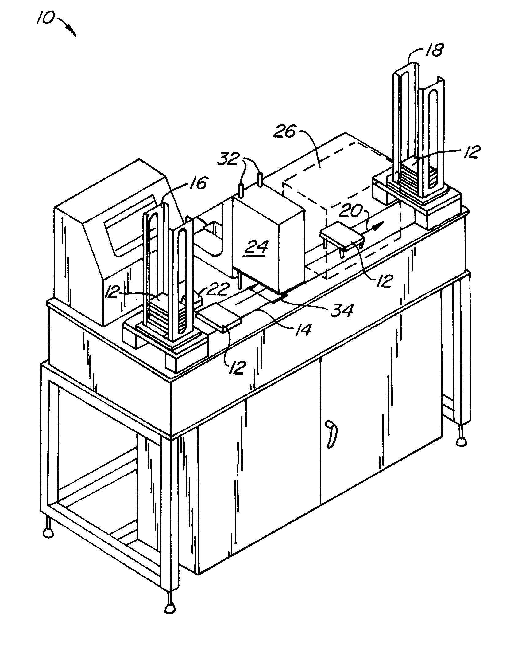
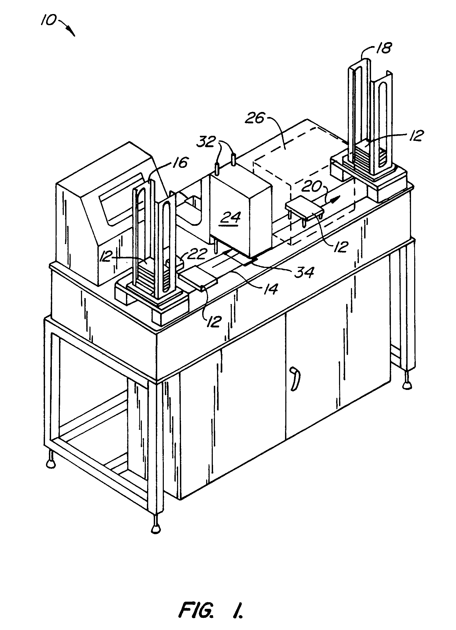
[0010]The present invention generally provides improved systems, devices, and methods for analyzing a large number of sample compounds. In many embodiments, the samples will be contained in standard multi-well microtiter plates, such as those having 96, 384, 1536, or higher numbers of wells. These multi-well plates will typically travel along a conveyor system between an input stack and an output stack. One or more test stations, each having a microfluidic device, will be disposed along the conveyor system. At the
test station, each multi-well plate can be removed from the conveyor, and the wells of the multi-well plate will typically be sequentially aligned with an input port of the microfluidic device. After at least a portion of each sample has been injected into the
microfluidic channel system, the plate will be returned to the conveyor system. Pre and / or post
processing stations may be disposed along the conveyor system, and the use of an X-Y-Z
robotic arm and a novel plate support bracket allows each of the samples in the wells to be accurately introduced into the microfluidic network. This arrangement avoids having to move the microfluidic device or its port between entering of the samples, significantly simplifying the
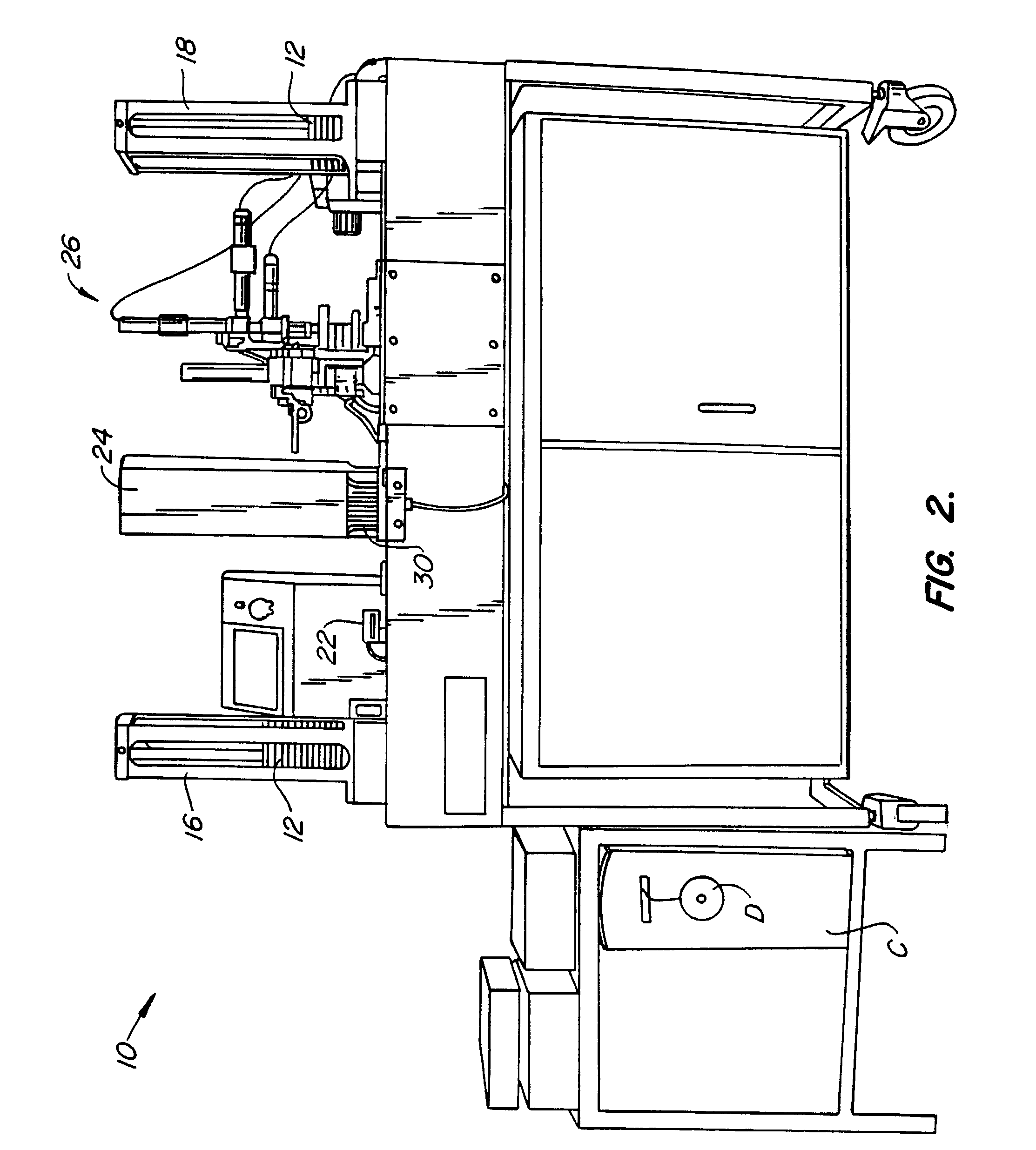
chip interface structure. In the exemplary embodiment, a
clamshell structure having a hinged lid releasably supports the
chip while providing and / or accommodating the electrical, fluid, optical, structural, and any other interface connections between the microfluidic device and the surrounding high
throughput system.
[0012]Preferably, a microfluidic device interface structure supports the microfluidic device (and its port) at a
fixed position. This interface structure will preferably comprise a
clamshell having a lid pivotally coupled to a base so as to restrain the microfluidic device therebetween. A window through the lid or base facilitates optically
coupling an optical detection system to the channel system of the microfluidic device for monitoring an optical characteristic of a reaction within a channel system. Electrodes extending from the base or lid can couple an electrical
potential source to fluid within the channel system through
electrode ports of the microfluidic device for electrokinetically transporting the fluids within the
microfluidic channel system.
[0013]In the exemplary embodiment, the array comprises multi-well plates, and the transportation system for moving the plates from the conveyor system includes a
robot arm having at least two, and preferably
three degrees of freedom. Where the plates define a
planar array of wells, such a
robotic arm allows the port to be selectively aligned with any of the wells (along the X and Y axes), and allows the plate to be lifted to bring the sample within each well into contact with the input port (along the Z axis). By using a plate support bracket which is narrower than the plate, lifting pins adjacent to the conveyor system can engage exposed
peripheral portions of the plate's lower edge to transfer the plate between the bracket and the conveyor system. This avoids complex robotic grasping mechanisms supported by the robotic arm. Pre and / or post testing stations may be disposed along the conveyor system. Such stations might include a sample management
station, for example, a
card reader which enters data from a bar code affixed to each plate so as to identify the samples thereon. Alternatively, reaction stations may be positioned before and / or after the test
station, for example, to controllably dilute the samples contained in the wells of a plate prior to testing, for reconstituting test compounds in an
aqueous buffer, and the like. The use of a bi-directional
conveyor belt and / or programmable transportation mechanisms provides flexibility in defining different testing sequences. For example, a
single sample disposed within one well of a plate might be moved back and forth between a
dilution station and the test station to provide data at different reaction times, multiple concentrations, and the like.
[0022]Preferably, the array path defines a
closed loop, so that the reusable arrays are loaded with samples, the samples are moved to and tested in the microfluidic device, the tested arrays are cleaned of the tested samples, and the arrays are loaded with new samples continuously. This may allow the use of specialized arrays incorporating electrodes to facilitate electrokinetically introducing the samples into the microfluidic devices. Advantageously, such a reusable array system avoids the waste problems associated with large numbers of disposable multi-well plates when testing libraries of test compounds. Such libraries will typically include at least 1,000 different test compounds, the libraries preferably having at least 10,000 test compounds, and often having over 100,000 different test compounds.

