Refrigerant cycle apparatus

a cycle apparatus and refrigerant technology, applied in mechanical apparatus, refrigeration components, light and heating apparatus, etc., can solve the problems of difficult to obtain desired throttling effect, performance degradation, and increase compressive power, so as to reduce the pressure loss in the evaporator, reduce the compressive power, and enhance the performance coefficient

Inactive Publication Date: 2008-01-22
SANYO ELECTRIC CO LTD
View PDF17 Cites 13 Cited by
  • Summary
  • Abstract
  • Description
  • Claims
  • Application Information

AI Technical Summary

Benefits of technology

[0007]The present invention has been developed in order to solve a conventional technique problem, and performances are maintained or enhanced, and generation of clogging or a dimension of a capillary tube is reduced in a refrigerant cycle apparatus which is operated at a supercritical pressure on a high-pressure side.
[0013]According to the present invention, a refrigerant flow rate of the first compression element is decreased to reduce a compressive power, and a performance coefficient can be enhanced. Since the refrigerant flow rate in the evaporator drops, a pressure loss in the evaporator is reduced, and performances are enhanced. Furthermore, since an amount of the liquid phase refrigerant in the evaporator increases, heat conducting performances are enhanced, and general performances can be enhanced.
[0014]Especially, since the first pressure reducing device comprises the capillary tube on the upstream side of the refrigerant and the throttling means on the downstream side of the capillary tube, the refrigerant having a supercritical state is pressure reduced by the capillary tube. The refrigerant having the supercritical state has superior dissolving characteristics. Therefore, even when the inner diameter of the capillary tube is reduced to 0.1 mm or more and 0.4 mm or less as in the second invention, clogging with sludge, water content, and oil is not easily caused. Therefore, even when carbon dioxide is used as the refrigerant as in the fifth invention, and a pressure reducing degree has to be set to be large, a length of the capillary tube can be shortened to improve a space efficiency.
[0015]Moreover, when the throttling means of the first pressure reducing device comprises the expansion valve as in the third invention, a pressure resistance of the expansion valve may be low because of the capillary tube on the upstream side of the refrigerant. Furthermore, when the throttling means of the first pressure reducing device comprises the capillary tube as in the fourth invention, the pressure is reduced by the capillary tube on the upstream side. Therefore, even when a capillary tube having a usual inner diameter is used in the capillary tube on the downstream side, the dimension of the tube does not have to be lengthened.

Problems solved by technology

As a result, there has been a problem that a compressive power increases and performances degrade.
However, when a usual electronic expansion valve is used as such pressure reducing device, it is difficult to obtain desired throttling effects, and an appropriate control could not be performed.
However, when the inner diameter is excessively reduced, the capillary tube is clogged with sludge, water content, or oil, and there is a possibility that a trouble is generated in refrigerant circulation.

Method used


Image

  • Refrigerant cycle apparatus
  • Refrigerant cycle apparatus
  • Refrigerant cycle apparatus

Examples


embodiment 1

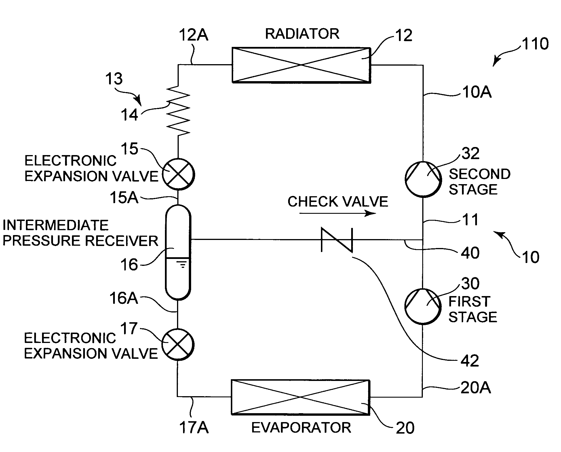
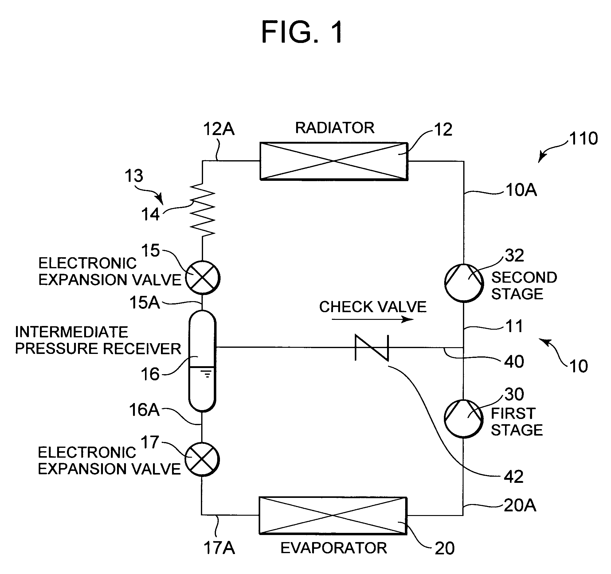
[0023]FIG. 1 is a refrigerant circuit diagram of a refrigerant cycle apparatus 110 according to one embodiment of the present invention. In the refrigerant cycle apparatus 110 of the present embodiment, a compressor 10, a radiator 12, a first pressure reducing device 13, an intermediate pressure receiver 16, a second pressure reducing device 17, and an evaporator 20 are successively connected to one another in an annular form to constitute a refrigerant circuit. That is, a refrigerant discharge tube 10A of the compressor 10 is connected to an inlet of the radiator 12.

[0024]Here, the compressor 10 of the present embodiment is a compressor of a two-stage compression system, having a first compression element 30 and a second compression element 32 for compressing a refrigerant compressed by the first compression element 30. In a sealed container (not shown), there are arranged a driving element, and the first compression element 30 and the second compression element 32 which are driven...

embodiment 2

[0048]Next, a second embodiment of a refrigerant cycle apparatus according to the present invention will be described. FIG. 3 is a refrigerant circuit diagram of a refrigerant cycle apparatus 210 of the present embodiment. It is to be noted that, in FIG. 3, components denoted with the same reference numerals as those of FIG. 1 produce identical or similar effects.

[0049]In FIG. 3, reference numeral 25 denotes a capillary tube which is throttling means of a first pressure reducing device 13 in the present embodiment. This capillary tube 25 has an inner diameter of 0.5 mm or more and 6 mm or less, and a dimension of 0.5 m or more and 2 m or less, and has heretofore been used.

[0050]That is, as described above in detail in the first embodiment, a refrigerant having a supercritical state is first pressure reduced by a capillary tube 14 having a small inner diameter, and accordingly the refrigerant can be sufficiently pressure reduced. Therefore, even when the conventional tube is used as ...

embodiment 3

[0052]The present invention is not limited to the above-described embodiment in which a second pressure reducing device comprises an electronic expansion valve. For example, as shown in FIG. 4, the second pressure reducing device may comprise a conventional capillary tube.

[0053]FIG. 4 is a refrigerant circuit diagram of a refrigerant cycle apparatus 310 of the present embodiment. Reference numeral 27 denotes a capillary tube which is the second pressure reducing device. In FIG. 4, components denoted with the same reference numerals as those of FIGS. 1 and 3 produce identical or similar effects.

[0054]Even in the present embodiment, in the same manner as in the above-described embodiments, a refrigerant having a supercritical state is first pressure reduced by a capillary tube 14 having a small inner diameter, and accordingly the refrigerant can be sufficiently pressure reduced. Therefore, an appropriate control is possible by a usual electronic expansion valve 15 disposed on a downst...


PUM


Abstract

In a refrigerant cycle apparatus which is operated at a supercritical pressure on a high-pressure side, for a purpose of maintaining or enhancing performances or reducing generation of clogging or a dimension of a capillary tube, a compressor has a first compression element, and a second compression element which compresses a refrigerant compressed by the first compression element, a gas phase refrigerant in an intermediate pressure receiver is sucked into the second compression element of the compressor, a liquid phase refrigerant in the intermediate pressure receiver is pressure reduced in a second pressure reducing device, and introduced into an evaporator, and the first pressure reducing device comprises a capillary tube on an upstream side of the refrigerant, and throttling means on a downstream side of the capillary tube.

Description

BACKGROUND OF THE INVENTION[0001]The present invention relates to a refrigerant cycle apparatus in which a compressor, a radiator, a first pressure reducing device, an intermediate pressure receiver, a second pressure reducing device, and an evaporator are successively connected to one another in an annular form to constitute a refrigerant circuit and which is operated at a supercritical pressure on a high-pressure side.[0002]In this type of conventional refrigerant cycle apparatus, for example, an air conditioner for cooling air in a room, a compressor, a radiator, a pressure reducing device, an evaporator and the like have heretofore been connected to one another in an annular form via piping to constitute a refrigerant cycle. Moreover, a refrigerant gas is sucked into a compression element of the compressor, and is compressed to form the refrigerant gas having high temperature and pressure. The gas is discharged, and flows into the radiator. In the radiator, a refrigerant radiate...

Claims


Application Information

Patent Timeline
Patent Type & Authority Patents(United States)
IPC IPC(8): F25B1/00
CPCF25B1/10F25B9/008F25B41/067F25B5/02F25B2309/061F25B2341/0662F25B2400/13F25B2400/23F25B2500/01F25B41/39F25B41/37
Inventor KAMIMURA, ICHIROMUKAIYAMA, HIROSHIIMAI, SATOSHIITSUKI, HIROYUKIOTAKE, MASAHISA
Owner SANYO ELECTRIC CO LTD
Why Eureka
Try Eureka