Information recording method, reproducing method, and recording/reproducing method utilizing holography

a technology of information recording and reproducing method, applied in the field of optical information, can solve the problems of affecting the miniaturization of the optical system, affecting the accuracy of information recording, so as to achieve the effect of enhancing the number of pixels per two-dimensional page data, reducing the enhancement of recording density, and reducing the distortion of information recording

Inactive Publication Date: 2008-01-22
OPTWARE
View PDF5 Cites 72 Cited by
  • Summary
  • Abstract
  • Description
  • Claims
  • Application Information

AI Technical Summary

Benefits of technology

[0012]If the number of pixels per two-dimensional page data displayed in the spatial light modulator is increased, recording density is enhanced and recording capacity can be increased if the multiplicity of multiplex recording is the same, because information quantity per recording hologram is increased. Furthermore, if the frame rate of the spatial light modulator is the same, transfer rate is also improved. In addition, the so-called code rate can be improved, data conversion efficiency can be enhanced, and recording capacity can be increased by improving the modulation system or the coding system for the two-dimensional page data.
[0014]Although the number of pixels per two-dimensional page data can be increased if the pixel pitch of the spatial light modulator is made finer, spatial frequency increases when the pixel pitch becomes smaller. If it is assumed that the wavelength of the laser is λ, the focal distance of the object lens is f, and the pixel pitch of the spatial light modulator is D, the order d of the diffraction is d=λ×f / D, which indicates that spatial frequency increases if the pixel pitch becomes smaller. An increase in spatial frequency means that the hologram formed when light is concentrated by the object lens is enlarged, and as a result, effect contributing to the enhancement of recording density is weakened because the occupied area per recorded hologram widens.
[0021]The objective of the present invention is to provide a new recording method, a reproduction method, and a recording / reproduction method which can solve the afore-mentioned, deeply-intertwined problems in digital volume holography. Moreover, the objective of the present invention is to further improve recording density and transfer rate.[Means for Solving the Problems]

Problems solved by technology

However, there are various inhibiting factors to these approaches.
First, if the aperture of an object lens is enlarged to increase the number of pixels per two-dimensional page data, the lens becomes, heavier, stronger power is required to drive the optical system such as the focus, tracking servo, and asking servo, and because inertial force is also greater, quick movement becomes difficult.
In addition, miniaturization of the optical system is obstructed because increasing the aperture of the object lens means increasing the diameter of the beam.
Furthermore, the increase in the diameter of the beam is problematic in the slimming-down of devices, as well.

Method used


Image

  • Information recording method, reproducing method, and recording/reproducing method utilizing holography
  • Information recording method, reproducing method, and recording/reproducing method utilizing holography
  • Information recording method, reproducing method, and recording/reproducing method utilizing holography

Examples


Embodiment Construction

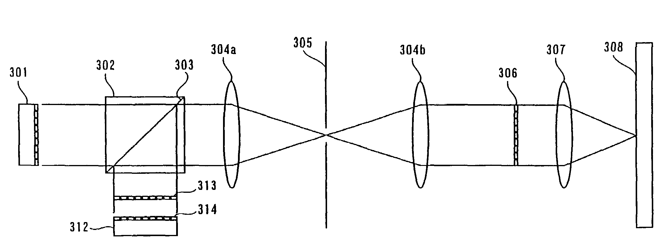
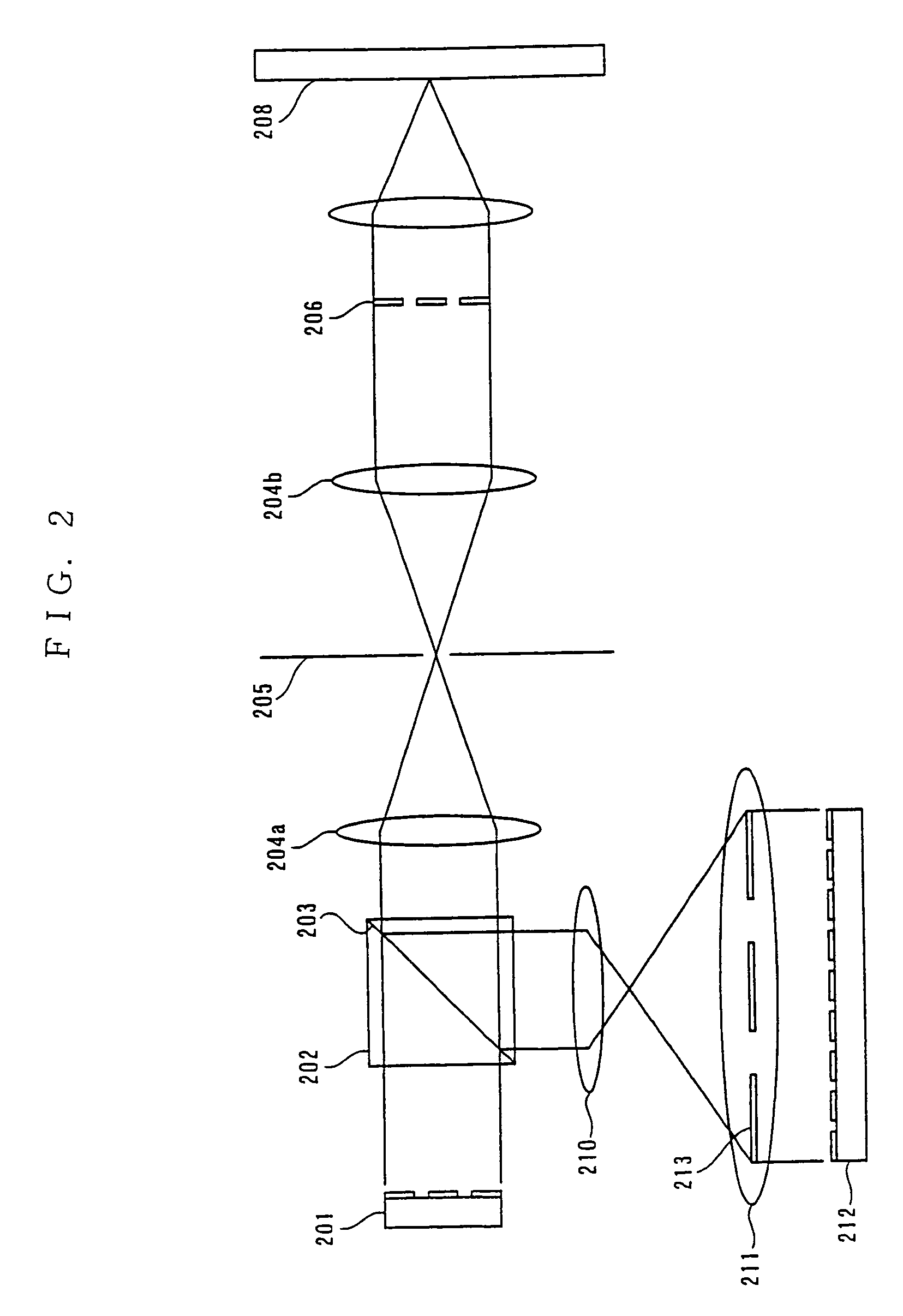
[0048]A recording method and digital pattern information displayed in a spatial light modulator are described below. Liquid crystal display panels, DMD (Digital Micromirror Device) and the like can be used as spatial light modulators.

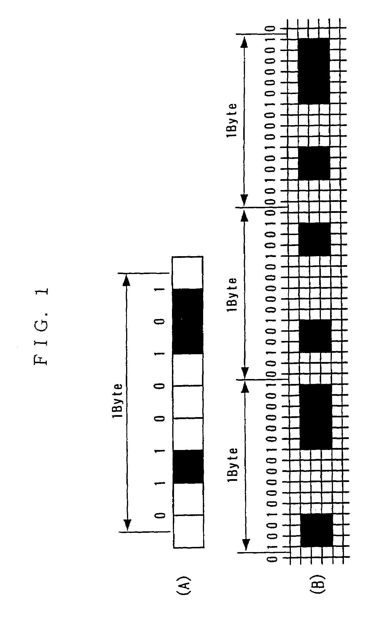
[0049]FIG. 1(A) is digital pattern information which is digital information expressed by the matching or mismatching of the attributes of adjacent pixels in a method according to the present invention and displayed in the spatial light modulator. In FIG. 1(A), if the attributes of the adjacent pixels do not match each other, digital information “0” is expressed, and if the attributes of the adjacent pixels match each other, digital information “1”, is expressed. The relation of the attribute and the correspondence of the digital information can be reversed. FIG. 1(A) expresses an 8-bit (1 byte) digital information which is “01100101”. Namely, the attributes the first and second pixels from the left in FIG. 1(A) are both white, expressing digital informa...


PUM

PropertyMeasurementUnit
thicknessaaaaaaaaaa
thicknessaaaaaaaaaa
angleaaaaaaaaaa

Abstract

A method for recording information on a recording medium utilizing an interference pattern by interference between an information light modulated spatially with digital pattern information displayed on a spatial light modulator having multiple pixels and a reference light for recording. In order to provide a novel recording method capable of enhancing the recording density and the transfer rate furthermore, digital information to be recorded is represented by match / mismatch of the attributes of adjacent pixels in the spatial light modulator to produce digital pattern information.

Description

BACKGROUND OF THE INVENTION[0001]1. Field of the Invention[0002]The present invention relates to an optical information recording method for recording information to an optical information recording medium through the use of holography, an optical information reproduction method for reproducing information from an optical information recording medium through the use of holography, and an optical information recording / reproduction method for recording information to an optical information recording medium and reproducing information from an optical information recording medium through the use of holography.[0003]2. Description of the Related Art[0004]Optical information recording / reproduction wherein information is recorded to and reproduced from an optical information recording medium through the use of holography has been implemented conventionally. In general, holographic recording for recording information to a recording medium through the use of holography is performed by superi...

Claims


Application Information

Patent Timeline
Patent Type & Authority Patents(United States)
IPC IPC(8): G11B7/00G11B7/0065
CPCG11B7/0065G11B7/013
Inventor HORIMAI, HIDEYOSHI
Owner OPTWARE
Why Eureka
Try Eureka