Plasma processing system

a processing system and plasma technology, applied in the field of plasma processing apparatus, can solve the problems of bending deformation, jeopardizing the processing uniformity, and failing to achieve uniform surface processing, and achieve the effect of uniform surface processing

Inactive Publication Date: 2008-01-29
SEKISUI CHEM CO LTD
View PDF31 Cites 18 Cited by
  • Summary
  • Abstract
  • Description
  • Claims
  • Application Information

AI Technical Summary

Benefits of technology

[0006]In order to solve the above problems, the present invention provides a plasma processing apparatus for plasmatizing (activating, ionizing and radicalizing are also included) processing gas in an electric field and then blowing it out, the plasma processing apparatus being characterized by comprising a pair of elongate electrodes which each have a first and a second elongate side edge and arranged in parallel, the electric field being applied between the pair of electrodes, an opening between the first elongate side edges serving as a processing gas receiving aperture, an opening between the second elongate side edges serving as a processing gas blowoff aperture; and a deforming preventive device that prevents the pair of electrodes from being deformed in a direction of arranging the electrodes in parallel. Owing to this arrangement, the electrodes can be prevented from being deformed by coulomb's force or due to difference in thermal expansion or the like at the time of application of electric field. Moreover, the interval between the electrodes can be prevented from becoming non-uniform. Thus, a plasma flow can evenly be blown off along the longitudinal direction of the electrodes and eventually, uniform surface processing can be executed.

Problems solved by technology

Thus, processing uniformity is failed.
This temperature difference causes a thermal expansion difference which results in bending deformation.
This again can jeopardize the processing uniformity.
Such deformation occurrable during the manufacturing process as just mentioned can also jeopardize the uniform flow of the plasma flow along the longitudinal direction of the electrodes.
This again can result in non-uniform processing.

Method used


Image

  • Plasma processing system
  • Plasma processing system
  • Plasma processing system

Examples


first embodiment

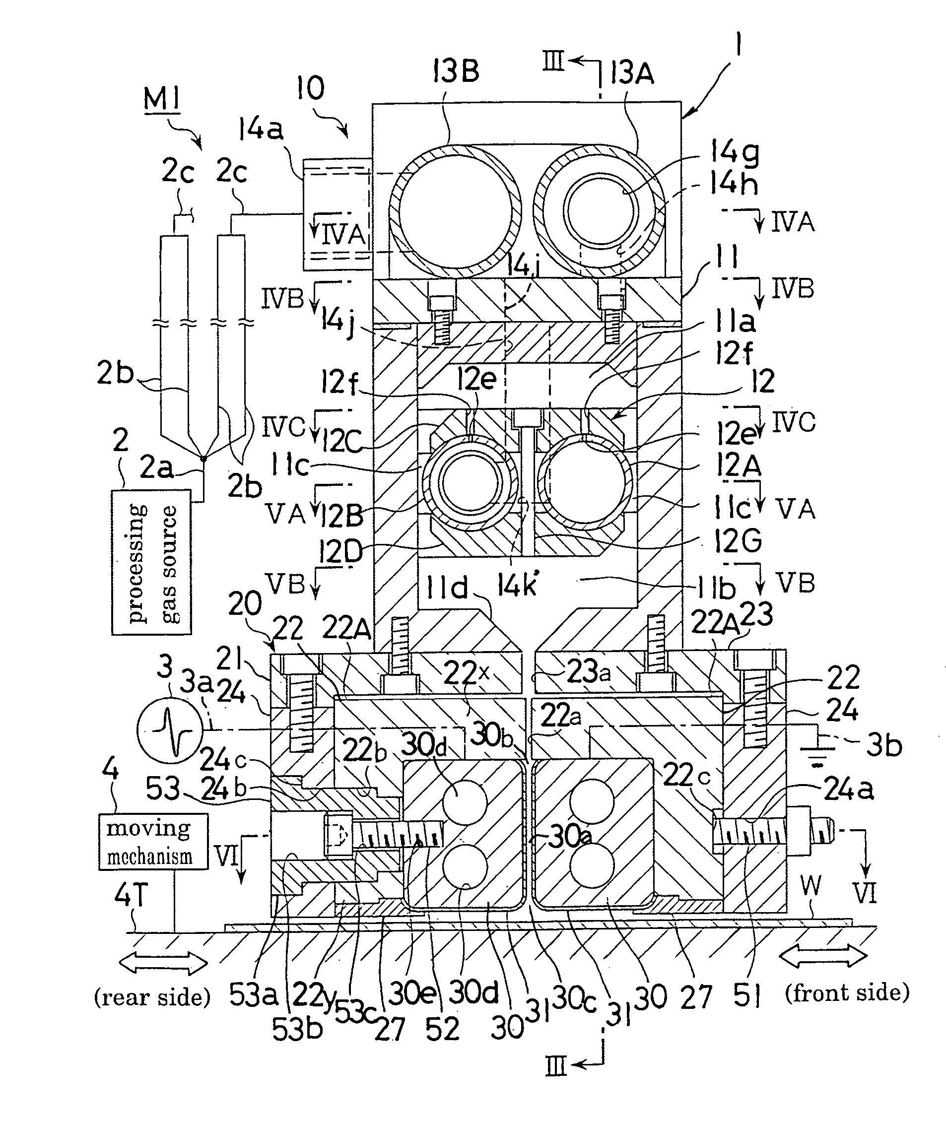
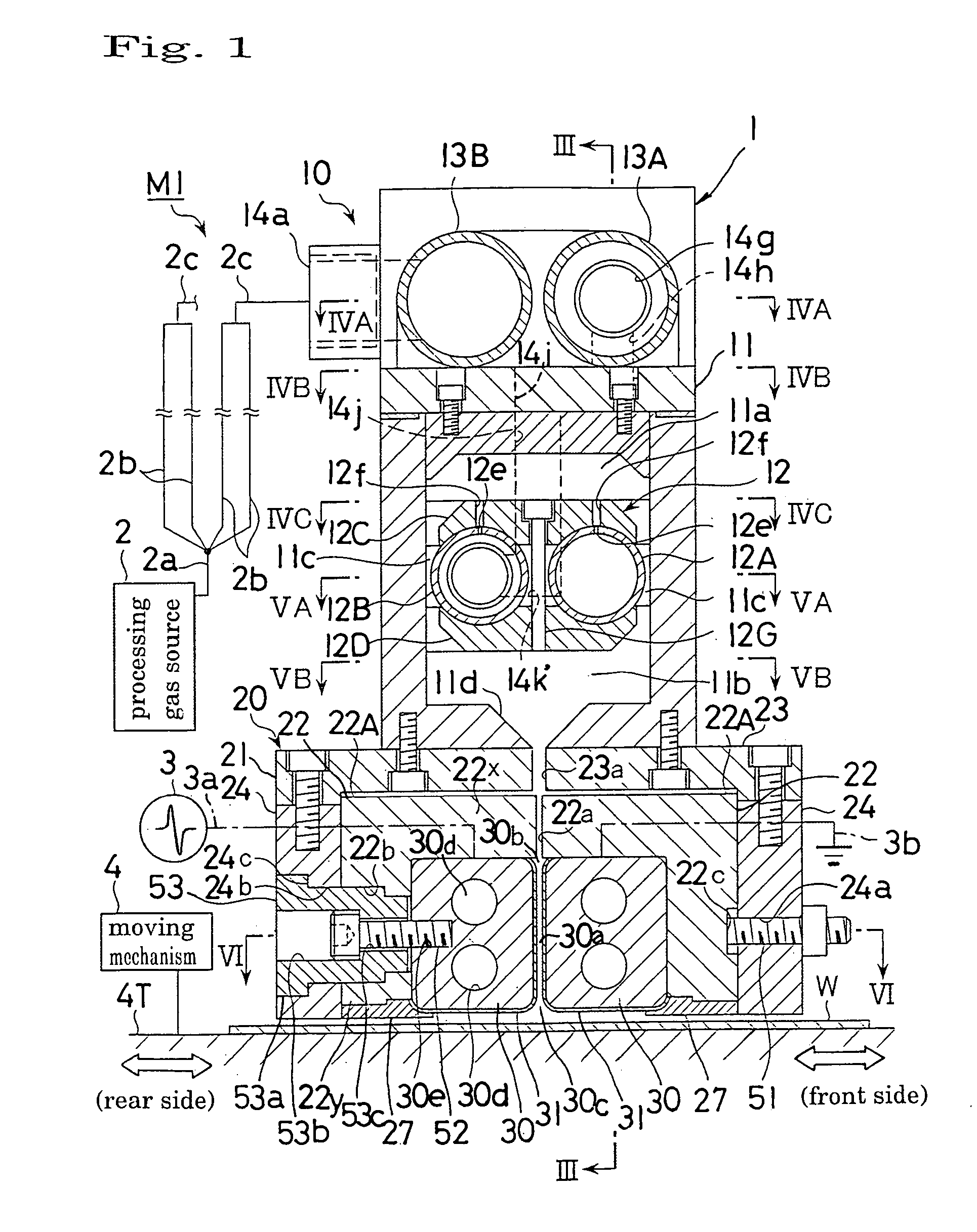
[0050]FIG. 1 shows a remote type normal pressure plasma processing apparatus M1 according to the present invention. The plasma processing apparatus M1 comprises a placement table 4T, a plasma nozzle head 1 disposed at an upper part of the placement table 4T and supported by a frame (not shown), a processing gas source 2 and a power source (electric field applying means) 3 which are connected the plasma nozzle head 1. A workpiece (substrate or substance to be processed) W having a large area is placed on the placement table 4T. A moving mechanism 4 is integrally connected to the placement table 4T. As indicated by arrows of FIG. 1, the placement table 4T and hence, the workpiece W are relatively moved in back and forth directions (left and right directions in FIG. 1) by the moving mechanism 4. It is also accepted that the placement table 4T is fixed and the head 1 is connected to the moving mechanism 4 so that the head 1 can move.

[0051]The power source 3 is such designed as to output...

second embodiment

[0108]As shown in FIGS. 7, 8 and 12, two (plural) spacers 60 (approach-deforming preventers) are disposed between the intermediate parts in the longitudinal direction of the pair of electrodes 30 in the Those spacers 60 are separately arranged leftward and rightward. Each spacer 60 is composed, for example, of a hard material having an insulative property and a plasma-proof property, such as ceramics. As shown in FIG. 11, each spacer 60 has a vertically elongate plate-like configuration. The left and right width of the spacer 60 is, for example, about 4 mm. The left and right edges of the lower part of the spacer 60 are slanted downward in such a manner as to be approached to each other as it goes downward, and they constitute the slant edge 60a (gas guiding part).

[0109]As shown in FIGS. 7, 8 and 11, the spacer 60 is one-sidedly arranged toward the upper side of the space 30a formed between the electrodes 30. That is, the lower part including the slanted edge 60a of the spacer 60 i...


PUM

PropertyMeasurementUnit
lengthaaaaaaaaaa
frequencyaaaaaaaaaa
electric field intensityaaaaaaaaaa

Abstract

A plasma processing apparatus M1 is provided with a processing part 20 for supporting a pair of elongate electrodes 30. The processing part 20 is provided with a plurality of pull bolts 52 (approach-deforming preventers) mutually spacedly arranged in the longitudinal direction of the electrode 30. A head part of each pull bolt 52 is hooked on a rigid plate 33 through a bolt holder 53, and a leg part thereof is screwed in the electrode 30. Owing to this arrangement, the electrodes 30 can be prevented from being deformed by Coulomb's force.

Description

TECHNICAL FIELD[0001]This invention relates to a plasma processing apparatus for executing such surface processing as film formation, etching, surface modification, organic contamination removal, cleaning, hydrophobicity, hydrophilicity, or the like, and more particularly to a remote type plasma processing apparatus which includes a pair of parallel long-sized electrodes, and in which processing gas is introducing from an opening between one longitudinal side edges of those electrodes to a space between the opposing surfaces of the electrodes so that plasma is generated, and the plasma thus generated is blown off of the electrodes from another opening between the other longitudinal side edges of the electrodes so that the plasma is applied to a substance to be processed.BACKGROUND ART[0002]The so-called remote type plasma processing apparatus is known in which processing gas is introducing between a pair of electrodes and plasmatized by glow discharge, then, this plasma flow is blow...

Claims


Application Information

Patent Timeline
Patent Type & Authority Patents(United States)
IPC IPC(8): H01L21/00H01J37/32H05H1/24H05H1/48
CPCH01J37/32009H01J37/3244H01J37/32541H05H1/48H05H1/24H05H1/34H01J37/32752H05H1/3478H05H1/46H01L21/3065C08J7/00
Inventor MAYUMI, SATOSHIHINO, MAMORUYASHIRO, SUSUMUSHIMIZU, HARUKAZU
Owner SEKISUI CHEM CO LTD
Why Eureka
Try Eureka