Check patentability & draft patents in minutes with Patsnap Eureka AI!

Method of forming inert anodes

Inactive Publication Date: 2008-01-29
ELYSIS LLP
View PDF10 Cites 1 Cited by
  • Summary
  • Abstract
  • Description
  • Claims
  • Application Information

AI Technical Summary

Benefits of technology

[0008]The above needs are met and object attained by providing a method of forming and firing an inert anode part comprising the steps: (a) providing a compressible hollow inert anode shaped mold having a closed bottom and an opening at the top; (b) inserting a metal mandrel into the center of the hollow inert anode shaped mold and adding compressible powder, selected from the group consisting of ceramic, cermet, metal, and mixtures thereof, into the hollow between the mandrel and the mold, so that the powder surrounds and contacts the bottom and sides of the outside of the mandrel and the inside of the mold, where the mandrel has raised male threads located around its top outside diameter near the opening of the inert anode shaped mold and a top exterior portion not contacting the powder; (c) compressing the powder and inert anode shaped mold causing the powder to compress against the mandrel to form recessed female grooves in the powder, matching the mandrel male threads and engaging the compressed powder to the mandrel forming an inert anode part; and then (d) vertically withdrawing the mandrel and engaged compressed powder inert anode part so that both are removed from the mold, and then (e) gripping the outside diameter of the compressed powder inert anode part and rotating the metal mandrel to unscrew the metal mandrel from the compressed powder inert anode part. The resulting female threads in the compressed powder inert anode part support downstream assembly requirements and eliminate the needs for any machining of the former interior annular groove. While still in the external gripping device, the inert anode part is inverted upside down (hollow side down) and placed on a firing substrate such as a setter tray in a heat source for firing to sinter it. The entire operation is performed at one production center, the inert anode part is manipulated with fewer handling devices, and no ceramic / cermet waste material is generated. The process is simple, less expensive, with a much higher production rate.

Problems solved by technology

Despite the common usage of carbon as an electrode material in practicing the process, there are a number of serious disadvantages to its use, and so, attempts are being made to replace them with inert anode electrodes made of for example a ceramic or metal-ceramiccermet” material.
Although ceramic and cermet electrodes are capable of producing aluminum having an acceptably low impurity content, they are relatively expensive.
This provides a variety of problems.

Method used


Image

  • Method of forming inert anodes
  • Method of forming inert anodes
  • Method of forming inert anodes

Examples


example

[0022]Successful application of a solid metal mandrel with external threads, such as similar to FIG. 4, for forming inert anodes has been demonstrated on a prototype automated cold isostatic pressing complex. The metal mandrel tested ranged from 1.5 in. to 3.0 in (3.05 cm to 7.6 cm) diameter and from 8 in to 10 in (20.3 cm to 25.4 cm) long.

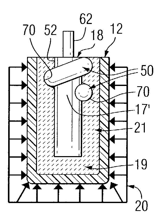
[0023]As shown in FIG. 3a, step 1, a ceramic / cermet powder was loaded into the inside bottom of a flexible mold; threaded mandrel was then placed on top of the powder and additional powder was added to fill the annulus between the outside of the mandrel and the inside of the mold. The mold / powder / mandrel assembly was then sealed and 20,000 psi-40,000 psi of isostatic pressure applied to the outside of the flexible mold. The flexible mold deformed under pressure, compressing the ceramic / cermet powder against the solid threaded mandrel. The isostatic pressure was relieved and the assembly was unsealed, exposing a consolidated / densified hollow anode ...


PUM

PropertyMeasurementUnit
Temperatureaaaaaaaaaa
Pressureaaaaaaaaaa
Electrical conductoraaaaaaaaaa

Abstract

A method of making an inert anode (12′) for use in an electrochemical cell first provides a hollow shaped mold (12) where a metal mandrel (17′) having raised male threads (50) at its top diameter (52) is inserted into the mold (12) and a compressible powder (19, 21) added, then the powder is compressed to form recessed female grooves (70) matching the mandrel threads (50) where the mandrel (17′) is engaged and withdrawn along with the compressed powder inert anode after which the mandrel is rotated to unscrew it from the compressed powder and the compressed powder shape is then placed on a tray (27) and heated to sintering temperature.

Description

FIELD OF THE INVENTION[0001]This invention relates to a mandrel and its use in the process of forming unsintered inert anodes used in metal electrolysis processes.BACKGROUND OF THE INVENTION[0002]A number of metals including aluminum, lead, magnesium, zinc, zirconium, titanium, and silicon can be produced by electrolysis processes. Each of these electrolytic processes preferably employs an electrode having a hollow interior.[0003]One example of an electrolysis process for metal production is the well-known Hall-Heroult process producing aluminum in which alumina disso fluoride bath is electrolyzed at temperatures of about 960° C.-1000° C. As generally practiced today, the process relies upon carbon as an anode to reduce alumina to molten aluminum. Despite the common usage of carbon as an electrode material in practicing the process, there are a number of serious disadvantages to its use, and so, attempts are being made to replace them with inert anode electrodes made of for example ...

Claims


Application Information

Patent Timeline
IPC IPC(8): B28B5/00B28B7/00B22F5/00B28B3/00B28B7/30B28B13/06C25C3/12
CPCB22F5/003B28B3/003B28B7/303B28B13/06C25C3/12B22F7/08B22F3/04B22F5/06B22F2998/10B22F2999/00
Inventor LATVAITIS, J. DEANMILLER, RAYMONDCZEKAJ, STEVEN A.HOLMES, PATRICK W.
Owner ELYSIS LLP
Features
  • R&D
  • Intellectual Property
  • Life Sciences
  • Materials
  • Tech Scout
  • Unparalleled Data Quality
  • Higher Quality Content
  • 60% Fewer Hallucinations
Learn More