Method and device for generating multi-functional feedback

a multi-functional feedback and feedback technology, applied in the field of electronic devices, can solve the problems of not being able to generate feedback for various stimulus signals with a single integrated component, not having exactly the same (resonance) characteristics, and difficult to manufacture devices with exactly the same characteristics, etc., to achieve the effect of easy adjustment of feedback, low power consumption, and easy reduction of power consumption

Active Publication Date: 2008-01-29
GULA CONSULTING LLC
View PDF23 Cites 102 Cited by
  • Summary
  • Abstract
  • Description
  • Claims
  • Application Information

AI Technical Summary

Benefits of technology

[0018]The present invention has several advantages over the prior-art solutions. In the present invention, the resonating vibrating element(s) may be used to provide several different functions, whereas in the prior-art solutions each function requires a dedicated component in the implementation. This is a clear advantage.
[0019]The present invention represents a solution in which power consumption is low. This is a very important feature in electronic hand-held devices. In prior-art solutions, each feedback signal (e.g. a haptic feedback signal, a vibratory alert signal, an audio signal or a buzzer signal) must be generated with a dedicated component. In the present invention, on the other hand, all such feedback signals are generated with a single component and, therefore, there is only one power-consuming component. This enables power consumption to be more readily minimized.
[0020]The present invention also provides a solution in which it is not necessary to use conventional touch-sensitive displays. Electronic hand-held devices can be made much more durable because it is not necessary to use any elastic membranes or touch-sensitive displays. Instead, a rigid transparent lens covers the actual display device.
[0021]The solution represented by the present invention is simple. Furthermore, it is not prone to manufacturing differences because the feedback can be easily adjusted.
[0022]The present invention provides still further advantages. Because the solution uses only a single component to generate feedback, there is a significant space saving in the Printed Circuit Board (PCB). The number of components needed on the PCB is thus reduced. The present invention additionally provides a low-cost solution because of the savings in the components.

Problems solved by technology

There are, however, several problems when a touch-sensitive display is used as a primary information input device.
The main problem is that there is no solution for electronic devices for generating feedback for various stimulus signals with a single integrated component, and which provides a cost-effective solution coupled with minimal power consumption.
It is also difficult to manufacture devices with exactly the same (resonance) characteristics because of the mechanical tuning feature.
The solution is not applicable for generating feedback for various stimulus signals with a single integrated component.
However, the solution presented in this reference publication is not applicable for generating feedback for various stimulus signals with a single integrated component.
These displays, however, have weaknesses.
The display is vulnerable to external impacts.

Method used


Image

  • Method and device for generating multi-functional feedback
  • Method and device for generating multi-functional feedback
  • Method and device for generating multi-functional feedback

Examples


Embodiment Construction

[0029]Reference will now be made in detail to embodiments of the present invention, examples of which are illustrated in the accompanying drawings.

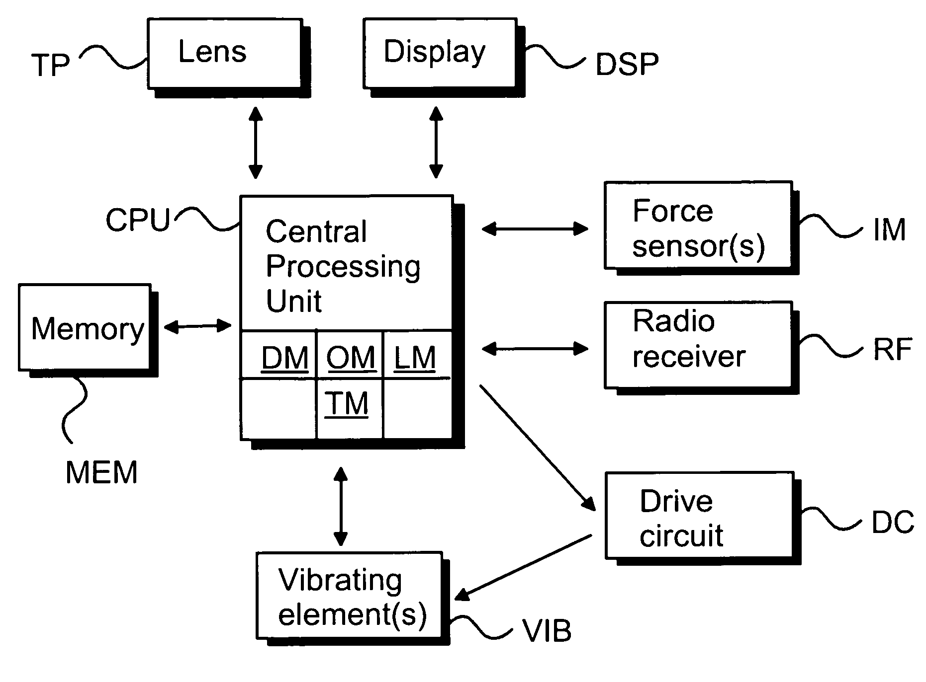
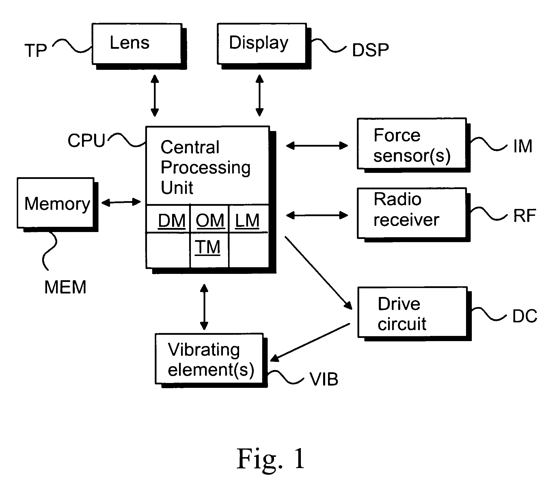
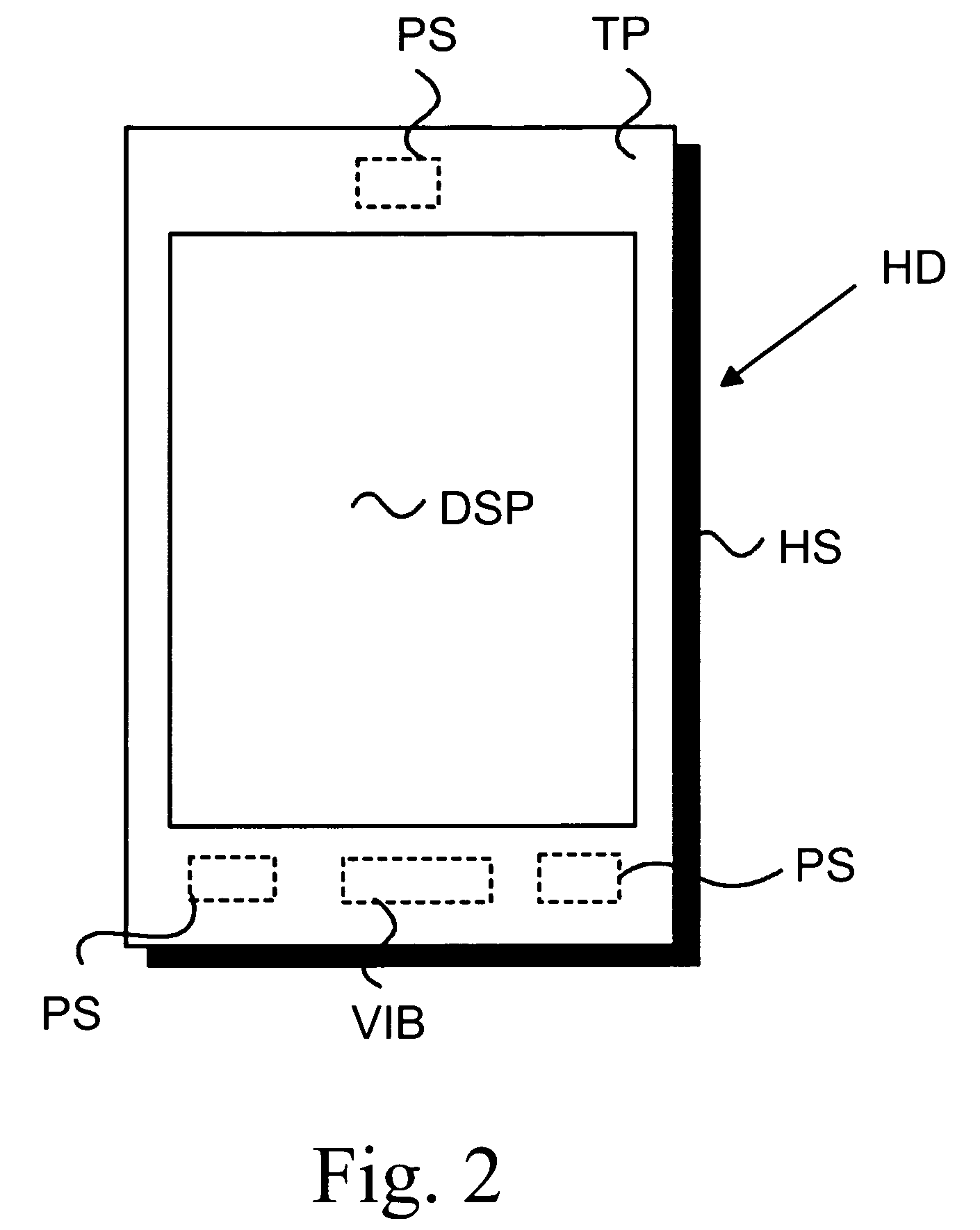
[0030]FIG. 1 is an electrical block diagram of an electronic hand-held device, e.g. a Personal Digital Assistant (PDA) or a mobile phone. FIG. 1 does not comprise all of the elements required in the electronic hand-held device but only the relevant elements in accordance with the present invention. The electronic hand-held device comprises a central processing unit CPU for controlling the electronic hand-held device. A memory MEM is associated with the CPU to store relevant software applications and other relevant information. The electronic hand-held device comprises at least a partially transparent lens TP which covers at least the display; the term touch panel may also be used when referring to the lens. The actual display DSP is located under the transparent lens TP area.

[0031]The lens TP is also used as a primary input device. User a...


PUM


Abstract

A method, a dynamic user interface and an electronic device for generating user-detectable multi-functional feedback using a single component in response to a stimulus signal. One or more resonating vibrating elements, such for example as a piezo-bender, are attached to a selected component of the electronic device. Because sensory feedback in the form of a haptic feedback signal, a buzzer signal, a vibratory alert signal and an audio signal are all generatable using such a piezo-element attached for example to a lens or housing of the device, a significant decrease in the space needed and in the required power consumption as compared to prior art devices, in which different feedback signals are generated using separate components, is realized.

Description

CROSS REFERENCE TO RELATED APPLICATION[0001]This is a continuation of International Application No. PCT / FI02 / 00889, filed Nov. 11, 2002 (now abandoned).BACKGROUND OF THE INVENTION[0002]1. Field of the Invention[0003]The present invention relates to electronic devices. In particular, the present invention relates to a novel and improved method, a dynamic user interface and an electronic device for generating user detectable multi-functional feedback.[0004]2. Description of the Related Art[0005]In information technology, the user interface (UI) is everything designed into an information device with which a human being may interact, including display screen, keyboard, mouse, light pen, the appearance of a desktop, illuminated characters, help messages, and how an application program or a Web site invites interaction and responds to it. In early computers there was very little user interface except for a few buttons at an operator's console. The user interface was largely in the form of...

Claims


Application Information

Patent Timeline
Patent Type & Authority Patents(United States)
IPC IPC(8): G09G5/00G06F17/00G06F3/01G06F3/041B06B1/06G06F1/16G06F3/00G06F3/033
CPCG06F1/1626G06F1/1684G06F3/016G06F3/041G06F2200/1637G06F2203/014
Inventor MOILANEN, HANNUKAMPMAN, VILLEVAANANEN, JOHANNES
Owner GULA CONSULTING LLC
Why Eureka
Try Eureka