Hot-swap circuit system for fan tray module

a circuit system and fan tray technology, applied in the direction of emergency protective arrangements, machines/engines, and pulse techniques, can solve the problems of voltage spikes and inrush currents, sparks, and application systems that crash, and achieve low manufacturing costs and large current and voltag

Active Publication Date: 2008-01-29
DELTA ELECTRONICS INC
View PDF5 Cites 19 Cited by
  • Summary
  • Abstract
  • Description
  • Claims
  • Application Information

AI Technical Summary

Benefits of technology

[0009]The invention is directed to a hot-swap circuit system for fan tray module, h

Problems solved by technology

At the moment of hot plugging a fan tray module in an application system and activating the fan tray module, the application system will generate voltage spikes and inrush currents while sending out sparks due to the power supply terminal thereof suddenly taking the load of the fan tray module.
The voltage spikes and inrush currents will mistakenly trigger the over-voltage protection device and the over-current protection device installed in the power supply terminal of the application system, and therefore crash the application system.
First, the analog controller IC 11 requires costly design and is expensive.
Second, the analog controller IC 11 cannot provide a wide range of voltage supply.
It can only provide the most negative voltage of −3 volts, and therefore the fan tray module is vulnerable to transient negative voltage when being hot-plugged into the application system (not shown in FIG. 1).
Thirdly, the driving capabil

Method used


Image

  • Hot-swap circuit system for fan tray module
  • Hot-swap circuit system for fan tray module
  • Hot-swap circuit system for fan tray module

Examples


Embodiment Construction

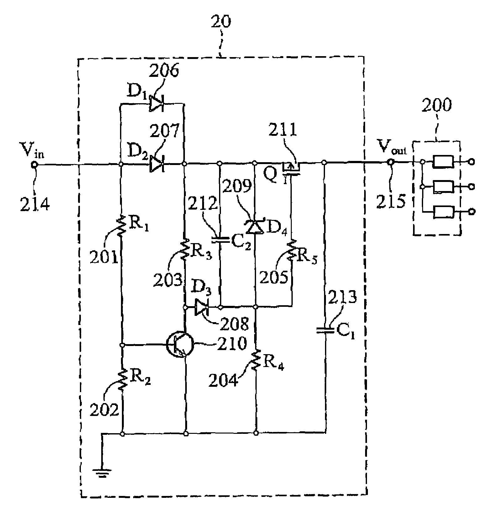
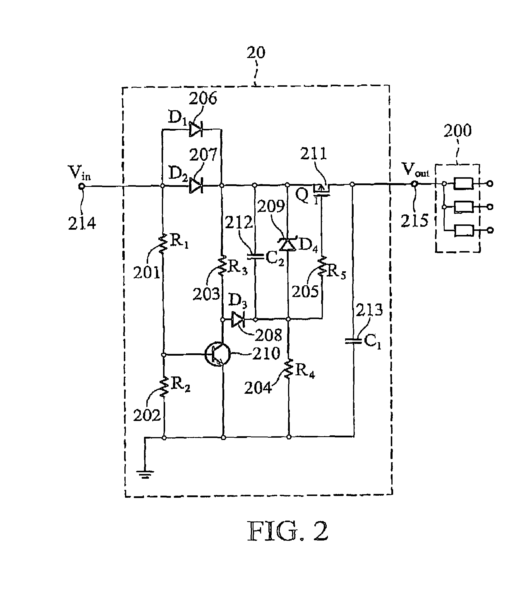
[0025]FIG. 2 shows a hot-swap circuit system for a fan tray module 200 according to an embodiment of the invention. The hot-swap circuit system comprises a soft-start circuit module 20 which is constituted of a set of resistors 201˜205 (R1˜R5), diodes 206˜209 (D1˜D4), a bipolar transistor 210, a field effect transistor for example a p-channel MOSFET 211 (Q1), and capacitors 212˜213 (C1˜C2).

[0026]The soft-start circuit module 20 through a voltage input terminal 214 receives an input voltage Vin output from a voltage source (not shown in FIG. 2) and through a voltage output terminal 215 provides voltage Vout to the fan tray module 200 and softly starts the fan tray module 200. In addition, the diodes 206˜209 conduct current in single direction, the resistors 201˜202 form a voltage divider, a base of the bipolar transistor 210 is electrically connected to one terminal of the resistor 202, and an emitter of the bipolar transistor 210 and the other terminal of the resistor 202 are ground...


PUM


Abstract

A hot-swap circuit system for fan tray module includes a soft-start circuit module in charge of the power start of the fan tray module hot-plugged into an application system. The soft-start circuit module includes a capacitor and a field effect transistor. The capacitor discharges and the field effect transistor turns off when an input voltage is changed from a certain value to zero.

Description

BACKGROUND OF THE INVENTION[0001]1. Field of the Invention[0002]The invention relates in general to a circuit system for a fan tray module. In particular, the invention relates to a hot-swap circuit system for a fan tray module.[0003]2. Brief Discussion of the Related Art[0004]At the moment of hot plugging a fan tray module in an application system and activating the fan tray module, the application system will generate voltage spikes and inrush currents while sending out sparks due to the power supply terminal thereof suddenly taking the load of the fan tray module. The voltage spikes and inrush currents will mistakenly trigger the over-voltage protection device and the over-current protection device installed in the power supply terminal of the application system, and therefore crash the application system.[0005]To avoid the described problems, a hot-swap circuit generally is provided to a fan tray module such that the fan tray module carries out a soft-start operation when plugge...

Claims


Application Information

Patent Timeline
IPC IPC(8): H02H9/08F04D13/06F04D15/00H02J1/00H02P7/00H03K17/08
CPCH02H9/004
Inventor CHEN, HUNTERCHIU, CHUN-LUNGHUANG, WEN-SHI
Owner DELTA ELECTRONICS INC
Why Eureka
Try Eureka