Centralized synchronization for wireless networks

a wireless network and synchronization technology, applied in the direction of synchronization arrangement, wireless commuication services, radio relay systems, etc., can solve the problems of complicated process, unsatisfactory oscillators, and inability to solve complex problems such as the delay in a wireless channel, so as to achieve the effect of undoing the distortion effect of the radio channel

Inactive Publication Date: 2008-01-29
TELECOMM RES LAB
View PDF28 Cites 57 Cited by
  • Summary
  • Abstract
  • Description
  • Claims
  • Application Information

AI Technical Summary

Benefits of technology

[0008]The second part of the synchronization process, correcting the signal, requires the use of an equalizer. The purpose of the equalizer is to undo the distortion effects of the radio channel. If properly configured, the equalizer will remove both the absolute delay and the delay spread of the radio channel for both signals going to and coming from the terminal. Therefore, sampling will occur at the correct time as if the radio channel did not exist. However, this condition only occurs when the base station and terminal oscillators are perfectly synchronized. An offset between the two oscillators will cause the information to be sampled at the wrong time. The synchronizer overcomes this problem by adjusting the equalizer coefficients to overcome the known offset between the oscillators, thus restoring the signals to their correct timing.

Problems solved by technology

These oscillators are not perfect and will be offset in time as well as frequency.
Two things complicate this process.
First, delay in a wireless channel is not a simple parameter due to the fact that the signal may take more that one path from the transmitter to the receiver, each with a different delay.
The other complication is that this network is designed to be asymmetric which means that the terminals themselves have little or no signal processing capabilities and cannot do complex analysis of the signals that they receive.
Therefore, all of the signals that are sent from the base station must be designed with the terminal's very limited capabilities in mind.
An offset between the two oscillators will cause the information to be sampled at the wrong time.

Method used


Image

  • Centralized synchronization for wireless networks
  • Centralized synchronization for wireless networks
  • Centralized synchronization for wireless networks

Examples


Embodiment Construction

[0033]In the claims, the use of the word “comprising” does not exclude other elements being present. The indefinite article “a” used in the claims does not exclude another one or more of that element being present.

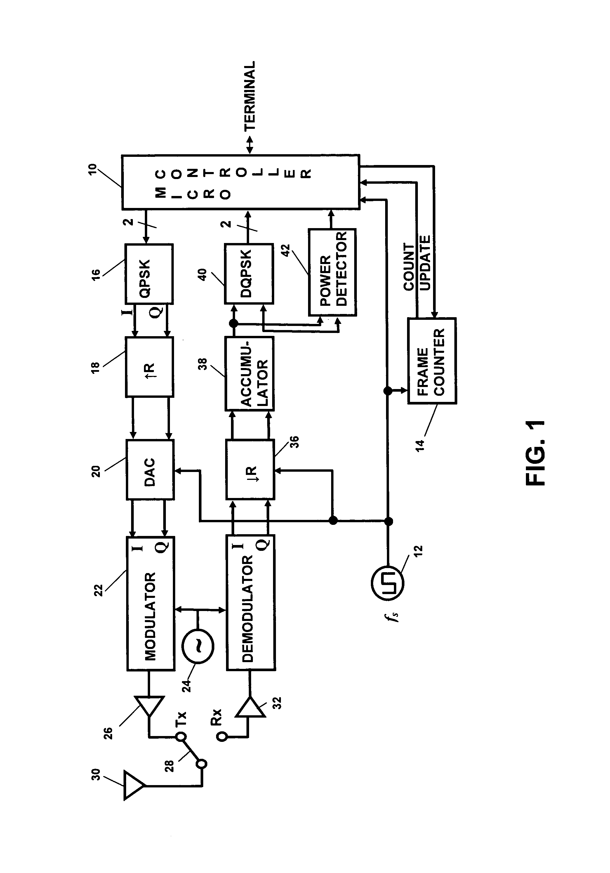
[0034]FIG. 1 shows the structure of one of the terminals in the network. Central to the terminal is a microcontroller 10, which handles all of the data, interfaces the data to the terminal, and all of the network and hardware protocols—including synchronization. A free-running oscillator 12 runs at the maximum symbol rate for the network (fs) and establishes when all events happen within the terminal. A typical symbol rate for this type of a terminal would be 100 MHz. Attached to the oscillator is a frame counter 14. Network time is divided into frames and events within the frame occur at a fixed number of clock cycles after the start of the frame. The frame counter simply counts the number of clock cycles of the oscillator 12 until the end of the frame is reached and then...


PUM


Abstract

This invention synchronizes the sample clocks of an entire wireless network from a single central base station. Unlike a conventional digital radio network where every terminal must have a synchronization circuit in its receiver to adjust the sample clock, each of the radio terminals in this network is clocked from an independent free-running oscillator. For each terminal, the base station learns the frequency and phase of the oscillator by exchanging a special set of signals: first a vernier signal to determine the initial time and frequency offset, and then an early-late signal to track changes in the oscillator. Once the base station is synchronized to the terminal's oscillator, it can determine the absolute path delay between itself and the terminal and correct for the delay using an equalizer. Signals received from the terminal are corrected after the signal arrives at the base station. Signals sent to the terminal are corrected within the base station before they are transmitted so they arrive at the terminal at the precise time that the terminal's free running oscillator takes a sample.

Description

BACKGROUND OF THE INVENTION[0001]A wireless LAN must provide a fast and reliable radio link between a base station and its terminals. A terminal in a wireless LAN is usually a portable device and therefore it is desirable to reduce the hardware requirements of the terminal as much as possible to make it inexpensive, small, and power efficient. The base station is part of the network infrastructure and usually has access to a reliable power supply so the hardware constraints on the base station are not as rigorous. Previous work (Asymmetric Equalization System for Data Transmission, Canadian patent application no. 2,234,777 published Oct. 15, 1999) has shown that radio equalization hardware can be implemented entirely in the base station, eliminating the need to put this complex and expensive hardware in every terminal. This is called an asymmetric design, because as much of the hardware as possible is moved to one side of the communication link. An asymmetric synchronization method ...

Claims


Application Information

Patent Timeline
Patent Type & Authority Patents(United States)
IPC IPC(8): H04J3/06H04B7/14H04Q7/20H04W56/00
CPCH04J3/0605H04L25/03343
Inventor MCGIBNEY, GRANT H.
Owner TELECOMM RES LAB
Why Eureka
Try Eureka