
Process and apparatus for increasing biological activity in waste treatment in bodies of water

a technology of biological activity and waste treatment, which is applied in the direction of energy-based wastewater treatment, chemical/physical processes, domestic heating, etc., can solve the problems of sludge clarification, increase the rate of oxidation of wastewater nutrients, etc., and achieve the effect of increasing the amount of oxygen injected and increasing the biological activity

Active Publication Date: 2008-02-12
ABSOLUTE AERATION
View PDF11 Cites 45 Cited by
  • Summary
  • Abstract
  • Description
  • Claims
  • Application Information

AI Technical Summary

Benefits of technology

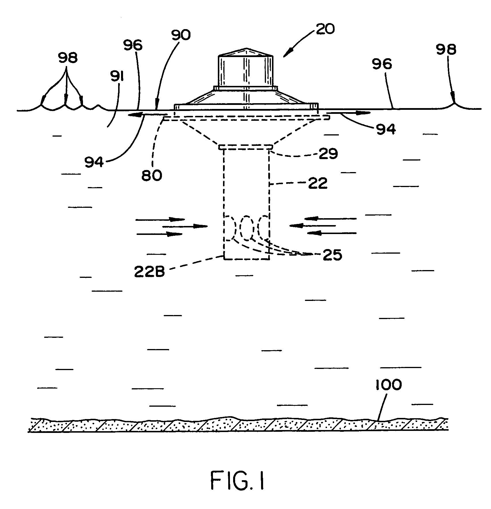
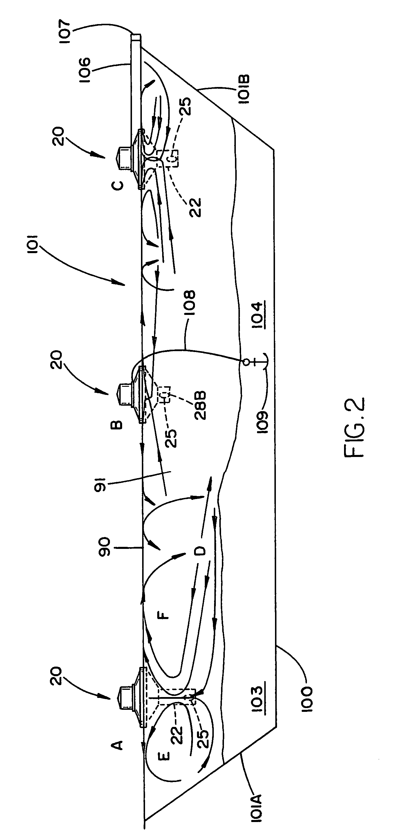
"The present invention is a process and apparatus for increasing biological activity in waste treatment bodies of water, such as ponds and lakes. It involves circulating fluid in a way that generates non-linear radial flow, which is magnified by the circulator's movement. This increases the amount of oxygen injected into the water, resulting in sludge clarification and faster oxidation of wastewater nutrients. The invention also involves mixing small air bubbles with the water to produce a low density fluid that increases sludge settling rate. A floating fluid circulator is used to circulate the fluid and generate waves in the water. Overall, the invention enhances the efficiency of waste treatment in water bodies."

Problems solved by technology

This increases the rate of oxidation of wastewater nutrients and results in sludge clarification.

Method used


Image

  • Process and apparatus for increasing biological activity in waste treatment in bodies of water
  • Process and apparatus for increasing biological activity in waste treatment in bodies of water
  • Process and apparatus for increasing biological activity in waste treatment in bodies of water

Examples


example 1

[0130]A floating fluid circulator 200, outside the scope of the present invention insofar as draft tube 205 was open at the bottom, was placed in a 20 feet deep, 5 acre dairy manure lagoon. The circulator was operated in the mix mode, e.g. counter-clockwise. Over time the vertically fed water drawn to circulator 200 resulted in the buildup of a conical mountain of sludge 207 ultimately resulting in plugging to tube 205.

example 2

[0131]The circulator 200 of Example 1 was replaced by circulator 20. Circulator 20 was identical to circulator 200 except that draft tube 203 replaced draft tube 205. Draft tube 203, in accordance with the present invention, included four inlets 202 which effectuated horizontal introduction of water. Over time the mountain of sludge dissipated and the quality of water improved.

examples 1 and 2

ANALYSIS OF EXAMPLES 1 AND 2

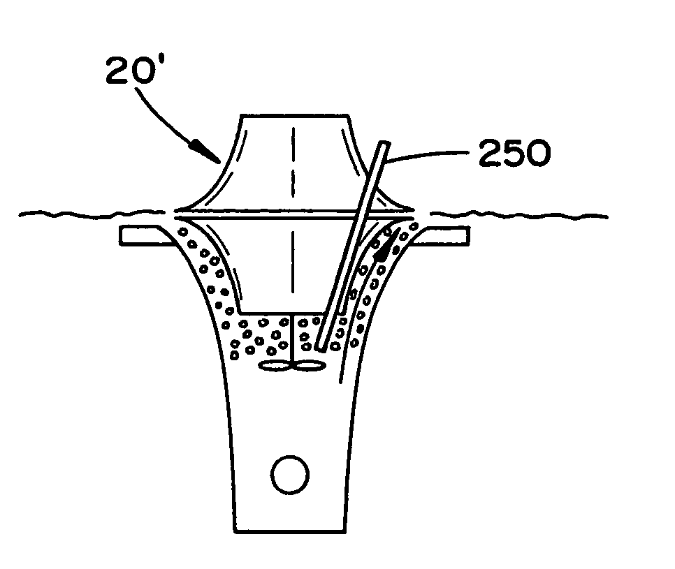
[0132]The impeller 201, as illustrated in FIG. 22A, imparts a swirl 204 to the fluid, drawn to it when the air-water fluid is introduced vertically into draft tube 205. In turn, this swirling induces swirling in the about to enter fluid. This swirling creates centrifugal forces which separate out microbe-rich solids which fall and deposit to form underwater sludge mountain 207.

[0133]When draft tube 203 was used fluid flowed horizontally into inlets 202 in a radial direction. No swirl was created so that no centrifugal force was created to separate solids which remained in suspension. This encouraged microbial growth, improving water quality and eliminating sludge buildup under the circulator 20.

EXAMPLE 3

[0134]A floating fluid circulator 20 was operated in mix mode. That is, impeller 201 was rotated in the counter-clockwise direction. In this rotation water flows in an upward direction, denoted in FIG. 22A by arrow 209. Specifically, the water flows from t...


PUM

PropertyMeasurementUnit
detention timeaaaaaaaaaa
diametersaaaaaaaaaa
heightaaaaaaaaaa

Abstract

A process and apparatus for increasing biological activity in waste treatment ponds and lagoons. In this process a floating fluid circulator having an annular space between nested frusto-conical surfaces is operated in a pond or lagoon. An aerator within the scope of the floating fluid circulator is provided. That aerator includes an upper float chassis having a frusto-conical configuration, a sectional diverter arranged in a lower portion of the upper float chassis, the sectional aerator having a lower diverter portion and motor driven means mounted on the upper float chassis connected to a rotatable impeller.

Description

CROSS-REFERENCE TO RELATED APPLICATION[0001]The present application claims benefit of U.S. provisional application Ser. No. 60 / 686,735, filed on Jun. 1, 2005.BACKGROUND OF THE DISCLOSURE[0002]1. Field of Invention[0003]The present invention is directed to a process and apparatus for increasing biological activity in ponds and lagoons. More particularly, the present invention relates to a process and apparatus which generates discrete flows in ponds and lagoons resulting in greater biological activity and consequent increase in situ sludge digestion.[0004]2. Background of the Prior Art[0005]Waste treatment ponds and lagoons are commonly employed to pretreat agricultural and industrial waste in a relatively inexpensive manner. Their disadvantages are the large land mass they occupy and their slow speed. It is thus unsurprising that they are commonly sited in rural and other low cost locations. Although the location of the pond or lagoon solves the size problems associated with this wa...

Claims


Application Information

Patent Timeline
Patent Type & Authority Patents(United States)
IPC IPC(8): C02F3/00
CPCB01F3/04609B01F3/04773B01F13/0049B01F13/1013B01F13/1022C02F3/165C02F7/00Y10S261/71Y02W10/37Y02W10/10B01F23/23341B01F23/23421B01F33/503B01F33/81B01F33/813
Inventor ROBERTS, RICKY EUGENEKEY, JAMES RHRODRICKBETTLE, III, GRISCOM
Owner ABSOLUTE AERATION
Learn More