
Conductive curable resin composition and separator for fuel cell

a technology of curable resin and separator, which is applied in the direction of electrochemical generators, sustainable manufacturing/processing, final product manufacturing, etc., can solve the problems of long time required for firing, inability to achieve adequate durability, and low productivity, etc., to achieve excellent conductivity, high packing content, and superior heat release properties

Inactive Publication Date: 2008-02-12
SHOWA DENKO KK
View PDF24 Cites 80 Cited by
  • Summary
  • Abstract
  • Description
  • Claims
  • Application Information

AI Technical Summary

Benefits of technology

The present invention relates to a conductive curable resin composition that can be used to produce a highly conductive fuel cell separator, an assembly for a cell, an electrode or a heat releasing plate with excellent thin-film thickness precision. The composition comprises a curable resin composition containing an elastomer and a carbon material, with a specific ratio and a specific carbon material. The composition can be shaped into an uncured sheet and then cured to exhibit excellent conductivity and heat release properties. The technical effects of the invention include high conductivity, superior heat release properties, and excellent thin-film thickness precision.

Problems solved by technology

The corrosion problem associated with metals has invited attempts to coat the surfaces with precious metals or carbon, but it has not been possible to achieve adequate durability, and the costs of coating have also been a problem.
Such fired materials exhibit high electroconductivity, but the long time required for firing lowers the productivity.
When a cutting step is necessary, the productivity is further lowered and costs are increased, such that numerous problems have prevented their future use as common materials.
Separators employing composites of a carbon-based filler and a resin require a drastically greater content of the carbon-based filler to exhibit high conductivity, but because a large amount of resin must be added to maintain moldability, it has been difficult to achieve sufficiently high conductivity.
It has also been attempted to shape the composition into a highly precise sheet by rolling or the like and harden it into a fuel cell separator shape, for the purpose of improving thickness precision which is a particularly important characteristic for fuel cell separators, but since the resulting sheet is not uniform when it contains a high content of carbon-based filler, it has been necessary to increase the amount of resin serving as the matrix.
As a result, it has not been possible to achieve adequate electrical conductivity and thermal conductivity.
When, for higher electrical conductivity, a firing step is included wherein the molded article is heated for a long period at a high temperature of 1000-3000° C., the length of time required for production is extended and the production process becomes complicated, thereby further increasing the cost.

Method used


Image

  • Conductive curable resin composition and separator for fuel cell
  • Conductive curable resin composition and separator for fuel cell

Examples


examples

[0096]The present invention will now be explained in greater detail by way of examples, with the understanding that they are in no way limitative on the invention.

[0097]The materials used were as follows.

Component (A) (Curable Resin Composition)

A1: Elastomer

[0098]NBR1 (acrylonitrile-butadiene rubber; Nipol DN003 by Nihon Zeon, Mooney viscosity (ML1+4 (100° C.): 78)

[0099]NBR2 (acrylonitrile-butadiene rubber; Nipol 1312 by Nihon Zeon, Mooney viscosity (ML1+4 (100° C.): unmeasurable due to liquid form)

[0100]EPDM (ethylene-propylene-diene rubber; EP25 by Nihon Synthetic Rubber, Mooney viscosity (ML1+4 (100° C.): 90)

[0101]SBR (styrene-butadiene rubber; SL574 by Nihon Synthetic Rubber, Mooney viscosity (ML1+4 (100° C.): 64)

A2: Radical Reactive Resin

[0102]ALE (allyl ester resin; AA101 by Showa Denko K.K.)

[0103]VE1 (vinyl ester resin; sample containing 5 wt % phenol novolac-based diallyl phthalate, by Showa Highpolymer Co. Ltd; viscosity: 2.1 (Pa-sec, 80° C.))

[0104]VE2 (vinyl ester resin; H...

example 16

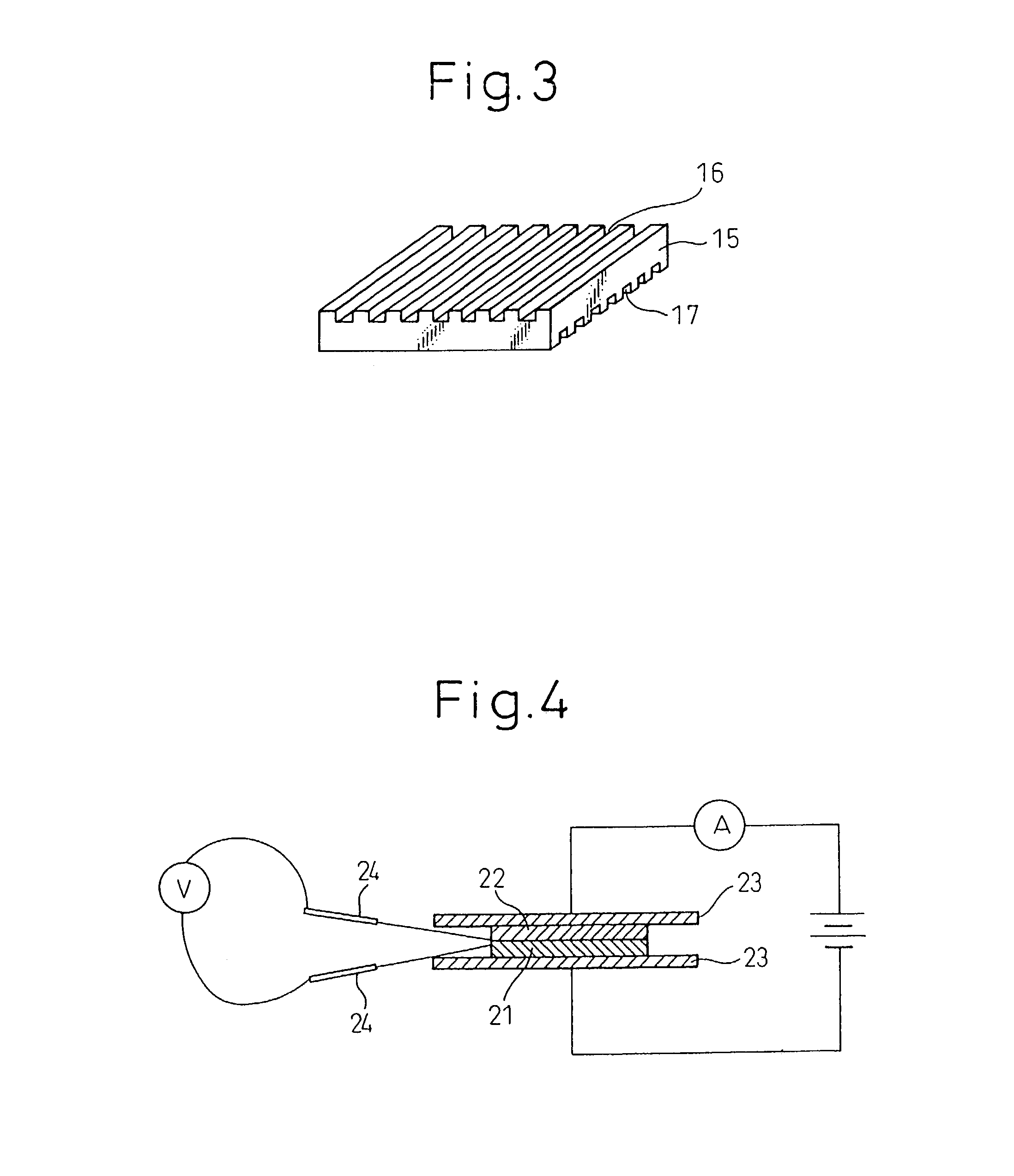
[0136]For Example 16, the composition used in Example 1 was formed into a 1.7 mm-thick uncured sheet using a 10-inch twin roll under conditions with a roll temperature of 60° C., a roll gap width of 1.7 mm and an equal rotation speed of 15 rpm, the uncured sheet was cut to a size of 280×200 mm and the cut sheets were inserted into a die capable of forming a plate with a size of 280×200×1.5 mm and having 1 mm-pitch grooves on both sides, and a 500 ton compression molding machine was used for 3 minutes of curing with a die temperature of 170° C. and a pressure of 60 MPa to obtain a double-side grooved cured body.

example 17

[0137]For Example 17, the composition used in Example 1 was extrusion molded into a 1.8 mm-thick, 70 mm-wide sheet using a 60φ single-screw extruder under conditions with a temperature of 60-90° C. and a rotation speed of 40 rpm, the uncured sheet was cut into sheets having a size of 200×70 mm and the cut sheets were placed in parallel into a die capable of forming a plate with a size of 280×200×1.5 mm and having 1 mm-pitch grooves on both sides, and a 500-ton compression molding machine was used for 3 minutes of curing with a die temperature of 170° C. and a pressure of 60 MPa to obtain a double-side grooved cured body.


PUM

PropertyMeasurementUnit
diameteraaaaaaaaaa
diameteraaaaaaaaaa
diameteraaaaaaaaaa

Abstract

There is provided a conductive curable resin composition comprising (A) a curable resin composition comprising an elastomer with a Mooney viscosity (ML1+4 (100° C.)) of 25 or greater at 2-80 wt % and (B) a carbon material, with a weight ratio of component (A) to component (B) of 70-5:30-95. The curable resin composition of component (A) preferably comprises (A1) an elastomer at 80-2 wt %, (A2) a radical reactive resin at 20-98 wt % and (A3) an organic peroxide at 0.2-10 parts by weight to 100 parts by weight of (A1+A2). Also provided are a process for production of a conductive cured resin by shaping and curing of the conductive curable resin composition, and a fuel cell separator, an assembly for a cell, an electrode or a heat releasing plate, obtained thereby.

Description

CROSS-REFERENCE TO RELATED APPLICATION[0001]This application is an application filed under 35 U.S.C. § 111(a) claiming benefit pursuant to 35 U.S.C. § 119(e) (1) of the filing date of the Provisional Application 60 / 316,983 filed Sep. 5, 2001, pursuant to 35 U.S.C. § 111(b).TECHNICAL FIELD[0002]The present invention relates to a conductive curable resin composition with excellent conductivity and heat release properties, and particularly it relates to a fuel cell separator, an assembly for a cell, an electrode or a heat releasing plate and to a process for their production.BACKGROUND ART[0003]Metals and carbon materials have conventionally been used for purposes requiring high conductivity. Carbon materials, in particular, being materials free of the corrosion that is characteristic of metals and exhibiting excellent heat resistance, lubricating properties, thermoconductivity and durability, have come to play an important role in fields such as electronics, electrochemistry, energy, ...

Claims


Application Information

Patent Timeline
Patent Type & Authority Patents(United States)
IPC IPC(8): C08K5/15B60C1/00C08K3/04C08K3/38H01M8/02
CPCB82Y30/00C08K3/04H01M8/0213H01M8/0221H01M8/0226C08L21/00Y02E60/50Y02P70/50
Inventor NOGUCHI, MASAYUKIKOBAYASHI, TOMOAKIIINO, TADASHI
Owner SHOWA DENKO KK
Learn More