Digitally controlled oscillator and associated method

a digital control and oscillator technology, applied in the direction of generator stabilization, pulse automatic control, pulse manipulation, etc., can solve the problems of implementing dcos, vcos that are sensitive to control noise or power supply noise, and the integration of both analog and digital components in the integrated circuit can be particularly difficult, so as to reduce the risk of frequency glitch

Active Publication Date: 2008-02-12
MARVELL ISRAEL MISL
View PDF9 Cites 48 Cited by
  • Summary
  • Abstract
  • Description
  • Claims
  • Application Information

AI Technical Summary

Benefits of technology

[0020]In yet another aspect of an embodiment of the invention voltage level shifting is achieved with substantially equal delay for low-to-high and high-to-low transitions. The level shifting circuit can be used to turn capacitors on and off equally fast, reducing the risk of frequency glitch during changes in ring oscillator frequency of operation.
[0021]One embodiment of the invention includes an input inverter including a first pull up transistor and a first pull-down transistor biased between a first voltage level and a second voltage level. The embodiment also includes an output inverter including a second pull up transistor and a second pull-down transistor biased between third voltage level and fourth voltage level. A voltage shifting circuit is provided that is operable to shift an output of the first inverter from the first voltage level to the third voltage level without inversion and is operable to shift an output of the first inverter from the second voltage level to the fourth voltage level without inversion. The voltage shifting circuit is operable to apply the shifted voltage to an input of the output inverter. Thus, the level shift circuitry shifts the voltage level without an inverter delay regardless of whether a higher or lower level input voltage is applied to the input inverter, and voltage shifts can occur substantially equally fast for high and low logic inputs to the first inverter.

Problems solved by technology

However, such prior VCOs often have been especially sensitive to control noise or power supply noise.
Moreover, integration of both analog and digital components in an integrated circuit can be especially challenging.
There have been problems with implementing DCOs, however.
Parasitic capacitance also can limit frequency range.
Power supply noise and ground noise can impact frequency stability.
Frequency glitches may occur during adjustment of oscillator frequency due to different switching delays for different capacitors, for instance.

Method used


Image

  • Digitally controlled oscillator and associated method
  • Digitally controlled oscillator and associated method
  • Digitally controlled oscillator and associated method

Examples


Embodiment Construction

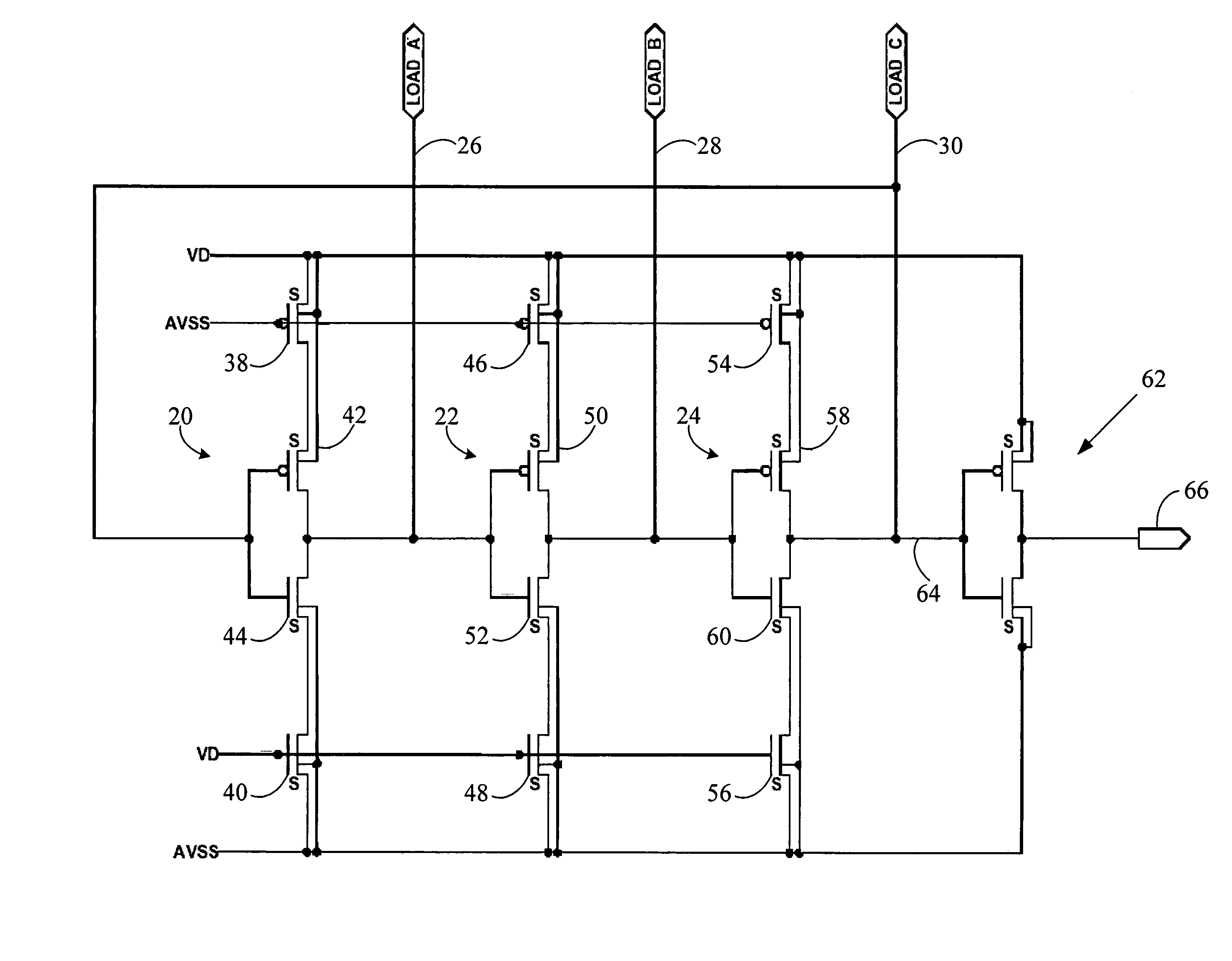
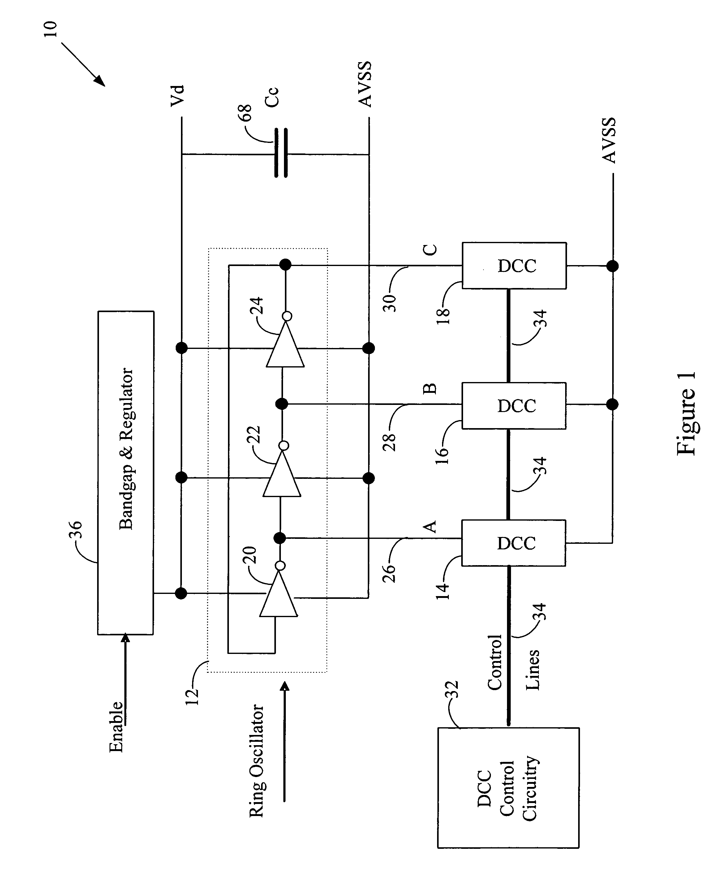
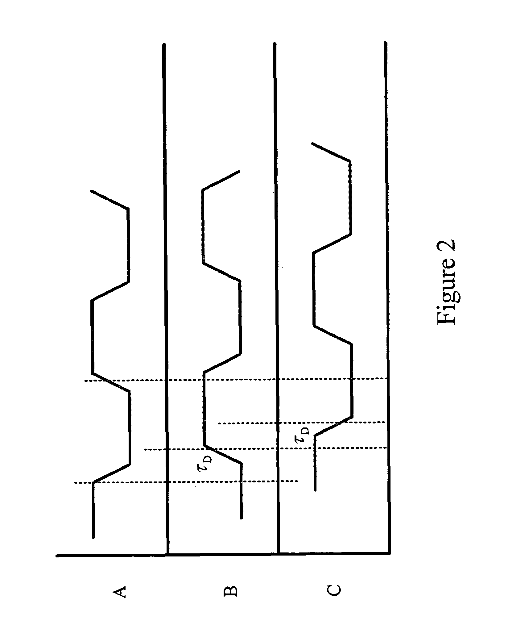
[0036]The following description is presented to enable any person skilled in the art to make and use a novel digitally controlled oscillator (DCO) and novel components thereof in accordance with the invention, and is provided in the context of particular applications and their requirements. Various modifications to the preferred embodiments will be readily apparent to those skilled in the art, and the generic principles defined herein may be applied to other embodiments and applications without departing from the spirit and scope of the invention. Moreover, in the following description, numerous details are set forth for the purpose of explanation. However, one of ordinary skill in the art will realize that the invention might be practiced without the use of these specific details. In other instances, well-known structures and devices are shown in block diagram form in order not to obscure the description of the invention with unnecessary detail. Moreover, in order to simplify the d...


PUM


Abstract

A digitally controlled oscillator circuit is provided that comprises a ring oscillator including multiple inverters; multiple digitally controlled capacitors (DCCs), each coupled to apply a digitally controllable amount of capacitance to an output of a different one of the inverters; and control circuitry operable to change an amount of capacitance applied to each inverter during operation of the ring oscillator and to cause the multiple DCCs to apply substantially the same amounts of capacitance to each of the inverter throughout operation of the ring oscillator.

Description

CROSS REFERENCE TO RELATED APPLICATION[0001]The present application claims benefit of earlier filed provisional patent application, U.S. Application No. 60 / 646,827, filed on Jan. 24, 2005, and entitled “DCO Methodology,” which is hereby incorporated by reference as if fully set forth herein.BACKGROUND OF THE INVENTION[0002]1. Field of the Invention[0003]The invention relates in general to integrated circuit oscillators, and more particularly, to digitally controlled oscillators (DCOs).[0004]2. Description of the Related Art[0005]Ring oscillators are important building blocks in many digital communications systems. For example, they are used in applications such as clock recovery circuits for serial data circuits communications, disk-drive read channels, on-chip clock distribution and integrated frequency synthesizers. A ring oscillator in its simplest form consists of an odd number of inverters connected in a circular chain. The circuit oscillates since it has no stable operation po...

Claims


Application Information

Patent Timeline
Patent Type & Authority Patents(United States)
IPC IPC(8): H03B5/04H03K3/03H03L1/00H03L5/02H03B5/24
CPCH03K3/0315H03K2005/00039H03K2005/00071H03K2005/00123H03K2005/00143
Inventor ASA, GILMOSHE, DAVIDBOURSTEIN, IDO
Owner MARVELL ISRAEL MISL
Why Eureka
Try Eureka