Liquid/coolant system including boiling sensor

a technology of liquid/coolant system and boiling sensor, which is applied in the direction of engine cooling apparatus, lighting and heating apparatus, applications, etc., can solve the problems of film boiling, damage or even catastrophic system failure, and slug boiling sta

Inactive Publication Date: 2008-02-19
PERKINS ENGINES
View PDF9 Cites 12 Cited by
  • Summary
  • Abstract
  • Description
  • Claims
  • Application Information

AI Technical Summary

Problems solved by technology

In internal combustion engine, for example, coolant that is in a nucleate boiling state, and particularly a slug boiling state, can undesirably depart from nucleate boiling during periods of high engine loading or after the a hot shut down when coolant is no longer circulating.
Similarly, in semiconductor chip cooling for example, prolonged operation of the semiconductor chips, such a microprocessors, at high loading or a rapid shut down of computing system could result in film boiling.
Thus, the coolant can transition instantly to a film boiling heat transfer regime in which the surface temperature Ts can rapidly rise to an extremely high temperature at which damage or even catastrophic system failure can occur.
However, with regard to internal combustion engines for example, the increasing stringency of engine emissions regulations is expected to result in more demanding heat rejection requirements as higher engine operating temperatures and cooled exhaust gas recirculation, for example, are used to reduce engine emissions.
However, systems such as described in U.S. Pat. No. 4,768,484 have shortcomings because they require multiple sens

Method used


Image

  • Liquid/coolant system including boiling sensor
  • Liquid/coolant system including boiling sensor
  • Liquid/coolant system including boiling sensor

Examples


first embodiment

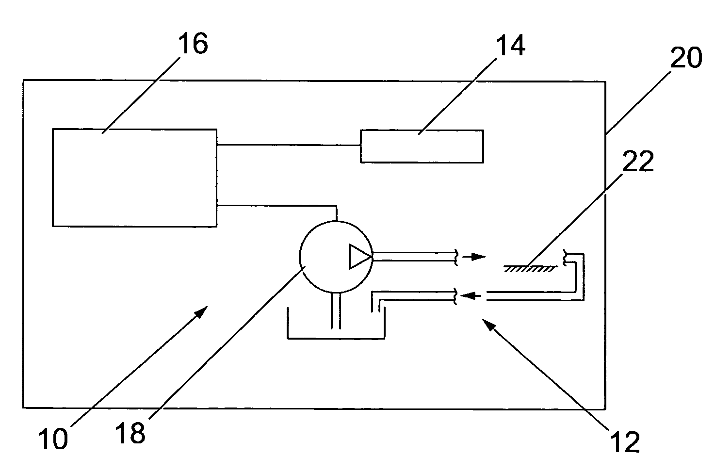
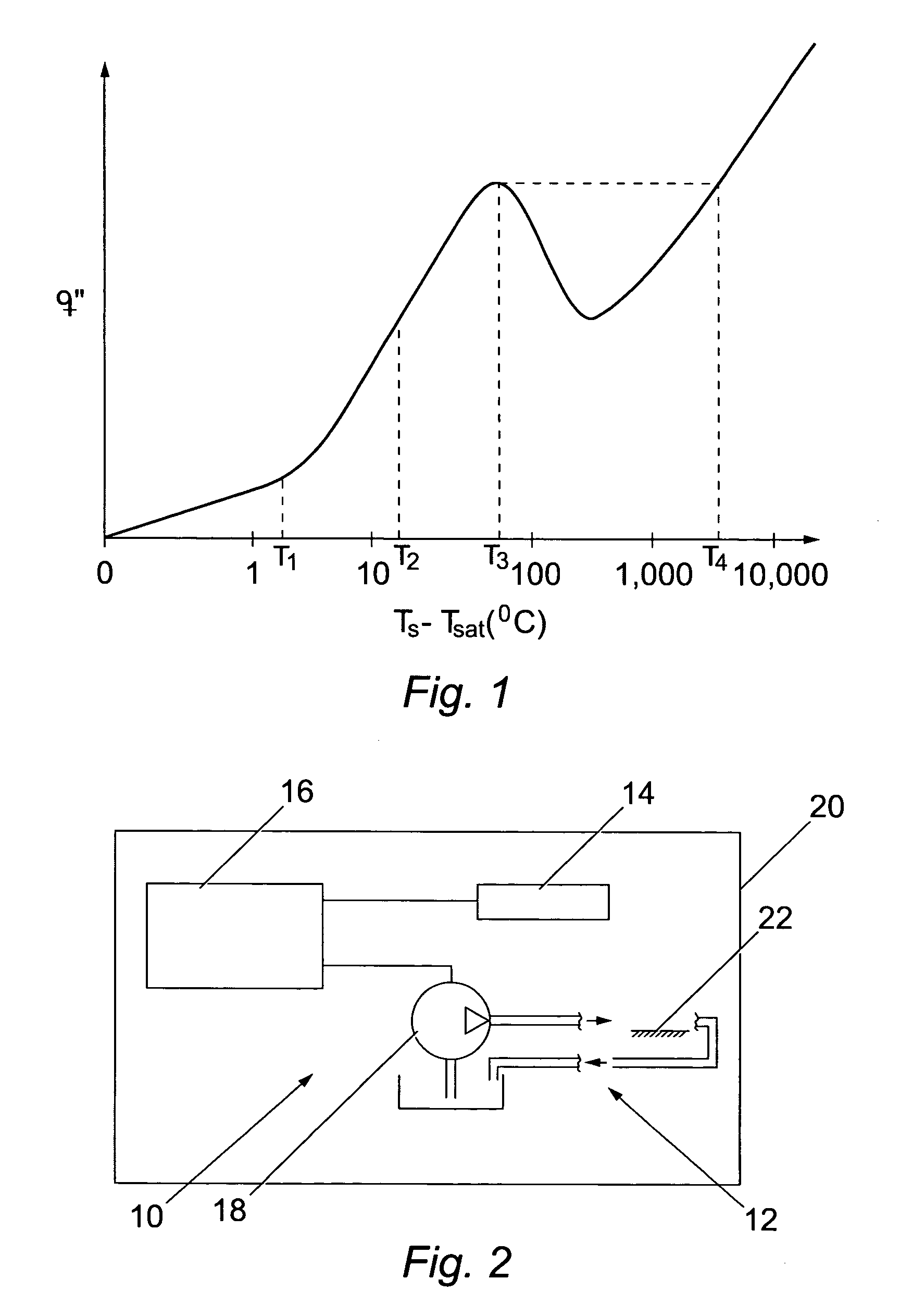
[0022]FIG. 2 diagrammatically illustrates a coolant system, generally designated 10, in accordance with this invention. The coolant system 10 comprises a coolant circuit 12, a sensor 14, a controller 16, and a pump 18. The coolant system 10 may be used with or form part of a device, generally designated 20, which is to be fully or partly cooled. The sensor 14 provides a signal to the controller 16 that is representative of fluctuations in the surface temperature Ts at or near a surface 22 in the coolant circuit 12. The controller 16 is capable of analyzing the sensor signal and, based on changes in one or more parameters of the sensor signal, changing the coolant flow adjacent to the surface 22.

[0023]In the embodiment of FIG. 2, coolant flow is changed by changing the output flow rate of the pump 18. As will be discussed in more detail below, the flow parameters of the coolant flow adjacent to the surface 22 can be changed to alter the heat transfer regime in which the coolant syste...

second embodiment

[0033]FIG. 8 illustrates a coolant system, generally designated 100, in accordance with this invention. This second and the further embodiments discussed below are similar to the coolant system 10 of FIG. 2 and like components are designated by like numerals. In the coolant system 100, controlling the flow of coolant through a coolant flow control valve, diagrammatically designated 102, changes coolant flow adjacent to the surface 22. The control valve 102 may be operated to change the flow of coolant therethrough to thereby change the flow of coolant adjacent to the surface 22. The control valve 102 may be a by-pass valve that allows a change in the coolant flow through a heat exchanger or it may be a flow directing valve to control the selective flow of lower temperature coolant toward the surface 22. The control valve 102 may be a two-way, on / off valve or it may be a proportional valve. Although not shown, those skilled in the art will also recognize that the coolant circuit 12 m...

third embodiment

[0034]FIG. 9 illustrates a coolant system, generally designated 200, in accordance with this invention. The coolant system 200 includes an indicator 202 that is activated in response to a change in at least one parameter of the signal from sensor 14. As will be described below, a change in the signal parameters can indicate that the coolant system has changed or is about to change boiling states and heat transfer regimes, and thus the indicator can indicate to the system operator intervention is needed to avoid or reverse an undesirable boiling state change. Alternatively, the coolant system 10 may automatically change coolant flow to avoid or reverse the state change, in which case the indicator could merely provide notice to the operator that a potentially damaging state change has occurred and should be investigated. The operator need not know the particulars of the boiling state, but instead only needs to know that activation of the indicator means some operator intervention is ...


PUM


Abstract

Coolant systems, for power sources (e.g. internal combustion engines, fuel cells, and nuclear reactors) or microprocessors for example, are beneficially operated with coolant in a nucleate boiling state, but transitions to damaging film boiling are then possible. The disclosed coolant system includes a sensor, such as a thermocouple or thermistor, that provides a signal representative of fluctuations in the temperature at a heated surface. The signal also includes at least one parameter. A controller processes the signal to determine changes in the parameter of the signal and/or to determine the state of the coolant and can responsively change the coolant flow to avoid undesirable coolant states. For example, coolant flow can be changed by changing the output of a coolant pump. The controller can change coolant flow automatically, or a signal can be provided to an operator that an undesirable coolant state change is imminent or has occurred, thereby allowing operator intervention. The system may also be used with liquids other than coolant.

Description

TECHNICAL FIELD[0001]This invention relates to liquid and / or coolant systems and, more particularly, to such systems in which a boiling sensor provides quantitative and / or qualitative information about liquid boiling that may be used to control liquid flow.BACKGROUND[0002]Liquid coolant systems can play a major role in the performance and safety of the device being cooled. For example, the coolant system can be especially important for power sources, such as internal combustion engines, fuel cells, and nuclear reactors, and for semiconductor chips such as microprocessors. In an internal combustion engine, the coolant system can be used to maintain engine operating temperature sufficiently high that the combustion system operates at or near peak efficiency while preventing engine temperatures so high that engine components are damaged. Likewise, the coolant system of a nuclear reactor is important in avoiding reactor damage and catastrophic reactor failure. In some fuel cells, coolan...

Claims


Application Information

Patent Timeline
IPC IPC(8): F25D17/00F25D23/12H05K7/20F01P3/00F01P3/22F01P7/14F01P7/16F01P9/00H01L23/34H01L23/427
CPCF01P3/22F01P9/00H01L23/34H01L23/427F01P7/164F01P2003/005F01P2007/146H01L2924/0002H01L2924/00
Inventor GARNER, COLIN PETERHOLLAND, ADRIAN
Owner PERKINS ENGINES
Why Eureka
Try Eureka