
Device for maintaining vascularization near an implant

a vascularization and implant technology, applied in the field of devices and vascularization maintaining near implants, can solve the problems of reducing the flow rate of filtrate along this path, reducing the clearance of various compounds from the body, and encapsulating cell implants often suffer from poor supply of nutrients and/or removal of metabolites from the implants themselves, so as to facilitate cell attachment and improve the mass transport properties of another implant , the effect of sufficient clearan

Inactive Publication Date: 2008-02-19
CYTOPHERX INC +1
View PDF42 Cites 26 Cited by
  • Summary
  • Abstract
  • Description
  • Claims
  • Application Information

AI Technical Summary

Benefits of technology

[0009]Another object of this invention is to provide a novel method and device for minimizing the need to administer angiogenic factors by way of, for example, injection, to a site near an implant, and more, specifically, a site near a bioartificial filtration device.
[0011]A still further object of this invention is to provide a novel method and device for maximizing output of other (i.e., non-angiogenic factor) cellular products from an encapsulated cell implant.
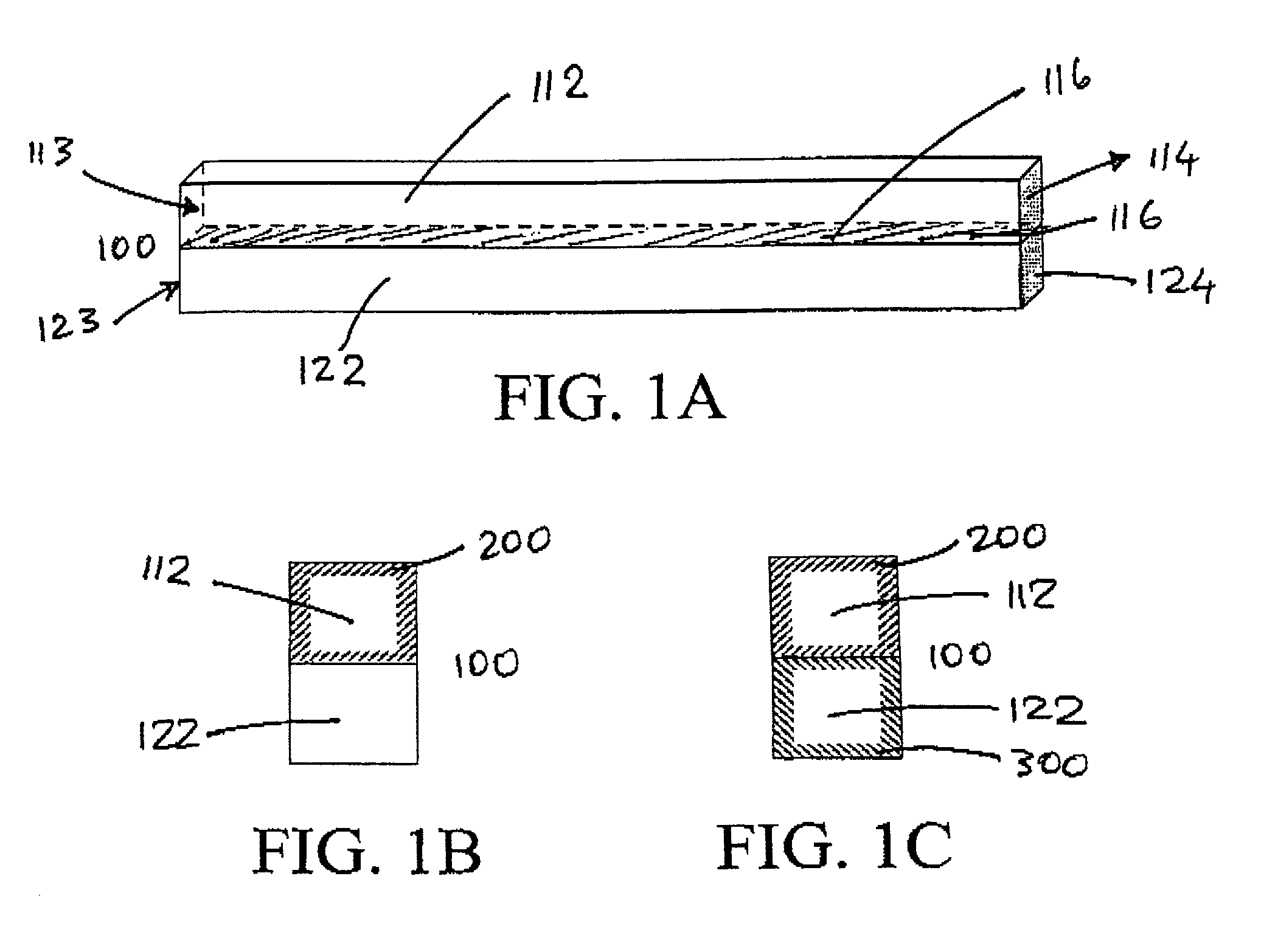
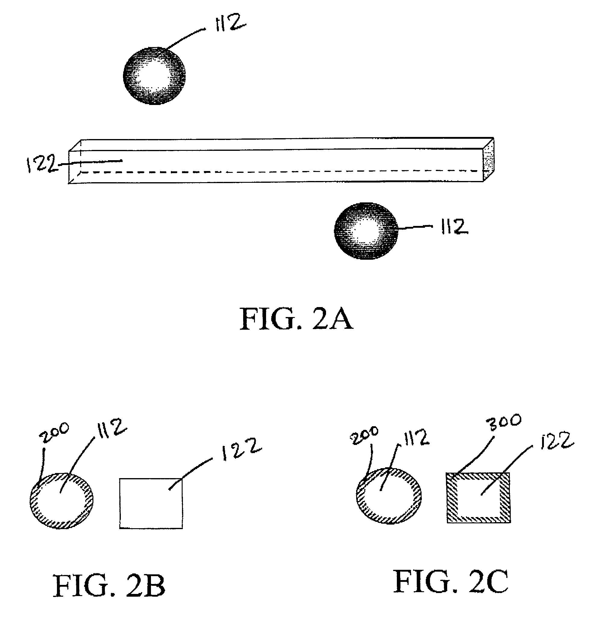
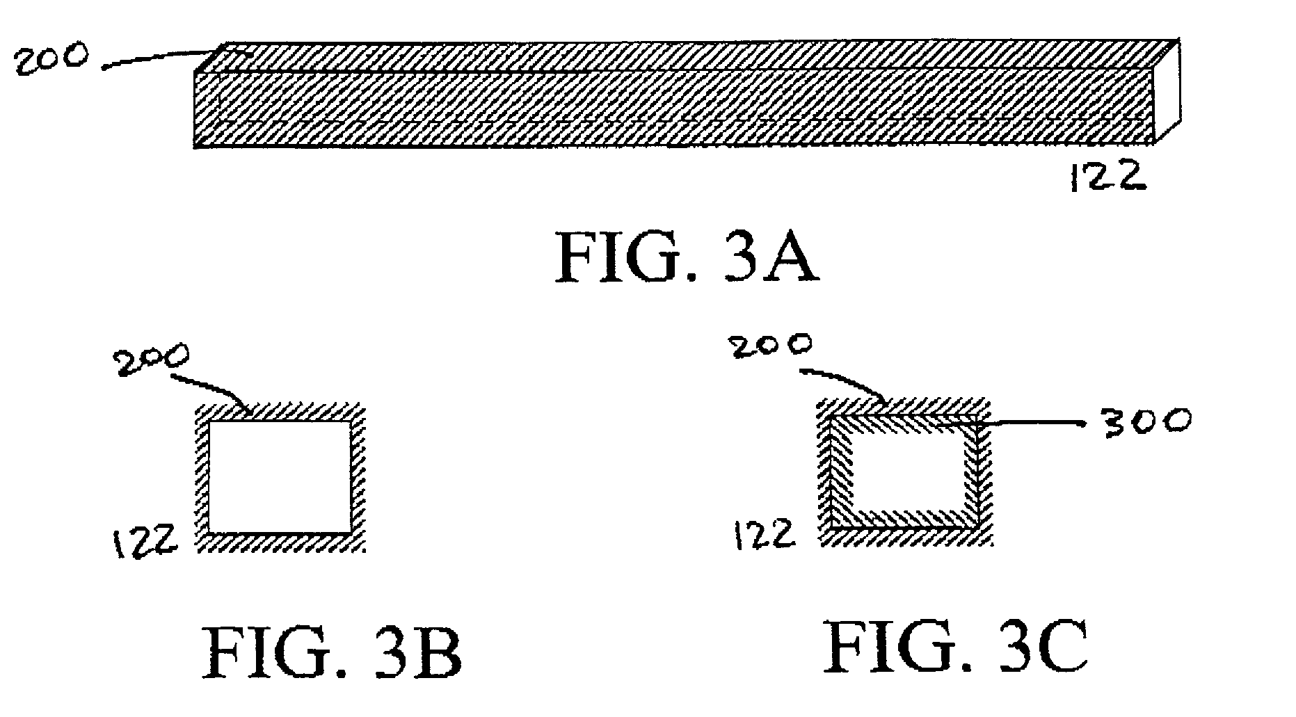
[0019]The resulting device would thus supply an implant, such as a bioartificial filtration device, with a supply of angiogenic factors from appropriate cells. This would prevent regression of capillary beds from the device and thereby maintain sufficient clearance therethrough and / or transport of metabolites and / or nutrients to and from the implant. In a preferred embodiment, the cells are myoblasts or myotubes transfected with genes coding for a selected angiogenic factor. The device may also include a fibrin glue layer to facilitate cell attachment.
[0020]Ultrafiltrate is collected in the device. In a further embodiment of the invention, the device could include one or more ports through which the generated ultrafiltrate could be directed to the urinary system or to a single transdermal port for collection ex vivo. Alternatively, ultrafiltrate could be directed in vivo to one or more tissue-engineered implants either for further processing, for example by an implantable bioartificial renal tubule, or to improve the mass transport properties of another implant, for example a bioartificial pancreas, or liver. Indeed, a hemofilter, whether synthetic or bioartificial, allowing passage of water, electrolytes, carbohydrates and proteins of low molecular weight, oxygen, and carbon dioxide will allow flux of cell, immunoglobulin, coagulation factor, and complement-free plasma to implanted cells.

Problems solved by technology

The net result is a decrease in the flow rate of filtrate along this path and a decrease in the clearance of various compounds from the body.
For example, encapsulated cell implants often suffer from a poor supply of nutrients and / or removal of metabolites from the implants themselves.
This commonly leads to encapsulated cell necrosis and reduced production of cellular products.

Method used


Image

  • Device for maintaining vascularization near an implant
  • Device for maintaining vascularization near an implant
  • Device for maintaining vascularization near an implant

Examples


example 1

[0122]Stereolithography, a uniquely powerful solid freeform fabrication technique, will be used for the iterative exploration and development of an implantable hemofilter device (1)-(5). The use of the Stereolithography Apparatus (SLA) will make it possible to design and fabricate many different hemofilter configurations quickly and precisely without requiring costly tooling.

[0123]The general approach will be to construct a series of flexible backbones in the SLA to support well defined arrangements of microporous hollow fibers. These hollow fibers will serve to either encapsulate genetically modified cells containing an angiogenic growth factor or to serve as hemofiltrate collection ducts. A design of such a device is illustrated FIG. 12. Pairs of fibers are arranged parallel to one another and fixed in place on the thin fiber backbone. Each alternating fiber is capped by the adhesive to create an interdigitated array of hemofiltrate and angiogenic fibers as illustrated in FIG. 12....


PUM

PropertyMeasurementUnit
hydraulic pressureaaaaaaaaaa
thickaaaaaaaaaa
thickaaaaaaaaaa

Abstract

A device and a method of maintaining vascularization near an implant, especially a bioartificial hemofilter. By associating cells that excrete angiogenic factors with such an implant, vascularization to the tissue surrounding the implant can be maintained. In a bioartificial hemofilter, this facilitates filtrate transport to a collection fiber for drainage from the body. The cells can be genetically engineered, for example using an adenovirus vector encoding for vascular endothelial growth factor. Myoblasts and myotubes may be used in one embodiment of the present invention.

Description

BACKGROUND OF THE INVENTION[0001]1. Field of the Invention[0002]The present invention relates to a device and a method of inducing and maintaining vascularization near an implant for the purpose of facilitating the formation of ultrafiltrate as well as facilitating the transport of oxygen, nutrients and metabolites to / from cells in the implant. More specifically, this invention relates to a device and a method of maintaining vascularization near a bioartificial hemofilter.[0003]2. Discussion of the Background[0004]One traditional approach to development of a bioartificial filtration device is to promote site-directed neovascularization in vivo near a mechanism for removing filtrate (see, for example, J. A. Thompson et al., Science 241, p. 1349-1352, 1988, the contents of which are incorporated herein by reference). In this approach, angiogenic factors (J. Folkman, and Y. Shing, J Biol. Chem. 267(16), p. 10931-10934, 1992 the contents of which are incorporated herein by reference) ar...

Claims


Application Information

Patent Timeline
Patent Type & Authority Patents(United States)
IPC IPC(8): C12M3/06A61F2/00C12N11/04C12N5/02A61M1/16A61BA61B1/00A61F2/01A61F2/02A61K9/22A61L27/00A61L27/14A61L27/38A61L31/00A61L31/16A61M1/14A61M1/34A61M1/36C12N5/06C12N5/08C12N11/02C12N11/08
CPCA61L31/005A61L31/16A61M1/1678A61F2/022A61L2300/258A61L2300/412A61L2300/414A61L2300/64A61M1/28B33Y80/00
Inventor HUMES, H. DAVIDFISSELL, WILLIAM H.BUFFINGTON, DEBORAH A.TZIAMPAZIS, EVANGELOS
Owner CYTOPHERX INC
Learn More