Photoelectric composite interconnection assembly and electronics device using same

a composite interconnection and photoelectric technology, applied in the direction of optical elements, instruments, optical waveguide light guides, etc., can solve the problems of easy generation of electromagnetic noises or adverse effects, difficult to ensure accurately the characteristic impedance of an electric interconnection, and difficult to speed up communication speed, etc., to achieve excellent flexibility and easy handling ability

Inactive Publication Date: 2008-02-19
HITACHI CABLE
View PDF13 Cites 39 Cited by
  • Summary
  • Abstract
  • Description
  • Claims
  • Application Information

AI Technical Summary

Benefits of technology

[0017]It is an object of the invention to provide a photoelectric composite interconnection assembly that develops an easy handling ability like ordinary electric cables with an electric connector while exhibiting excellent flexibility.
[0018]It is a further object of the invention to provide a photoelectric composite interconnection assembly that radiates little electromagnetic noise and has excellent noise resistance while allowing high-speed, high-capacity and high quality information transmission.
[0038]Moreover, according to the invention, since high-speed signals can be transmitted through the optical waveguide, noise resistance can be significantly improved while conducting high-speed, high-capacity and high-quality information transmission.
[0039]Furthermore, with the multiplexer and demultiplexer provided on the photoelectric composite interconnection assembly, multiplexed signals can be transmitted to allow a remarkable increase in transmission capacity. In this case, if the transmission capacity may be kept constant, the number of interconnections for optical signals can be reduced, and the number of the expensive electro-optic (E / O) conversion section and opto-electric (O / E) conversion section can also be reduced, and it is advantageous for lowering a cost.
[0040]Furthermore, when the photoelectric composite interconnection assembly is provided with plural electric connectors or electrodes connectable to a card edge connector, a freedom in interconnecting can be enhanced, whereby flexibility can be further improved. Thus, the connection between multiported electronics devices becomes easy.
[0042]When a termination resistance is provided in the vicinity of the electro-optic (E / O) conversion section or the opto-electric (O / E) conversion section, reflection of electric signals can be suppressed. Thus, quality of transmission can be enhanced to facilitate high-speed and high-capacity transmission.

Problems solved by technology

However, the conventional electric interconnection assemblies or optical interconnection assemblies involve the following problems.
Besides, its transmission loss in high frequency becomes remarkable, so that speedup in communications is difficult.
Moreover, it is also difficult to assure accurately an appropriate characteristic impedance of an electric interconnection because of a manufacturing deviation in sizing.
Furthermore, there are problems of generation of electromagnetic noises or being easily affected adversely by electromagnetic noises due to an electric interconnection system.
Although such a coaxial structure is excellent in electromagnetic noise proof strength, there is still no perfect means for solving the electromagnetic noise problem.
Thus, there is a slight generation of electromagnetic noises, and even such slight electromagnetic noises, they result in a problem in telecommunication equipment wherein weak electrical signals are handled.
In addition, it is difficult for the coaxial structure to achieve a miniaturization and a high-density fabrication.
In addition, there is such a problem that if a fine dust enters into the connecting section 1106, its optical connection loss becomes high, whereby a transmission quality deteriorates significantly.

Method used


Image

  • Photoelectric composite interconnection assembly and electronics device using same
  • Photoelectric composite interconnection assembly and electronics device using same
  • Photoelectric composite interconnection assembly and electronics device using same

Examples


Embodiment Construction

[0059]Preferred embodiments of the present invention will be described hereinafter by referring to the accompanying drawings.

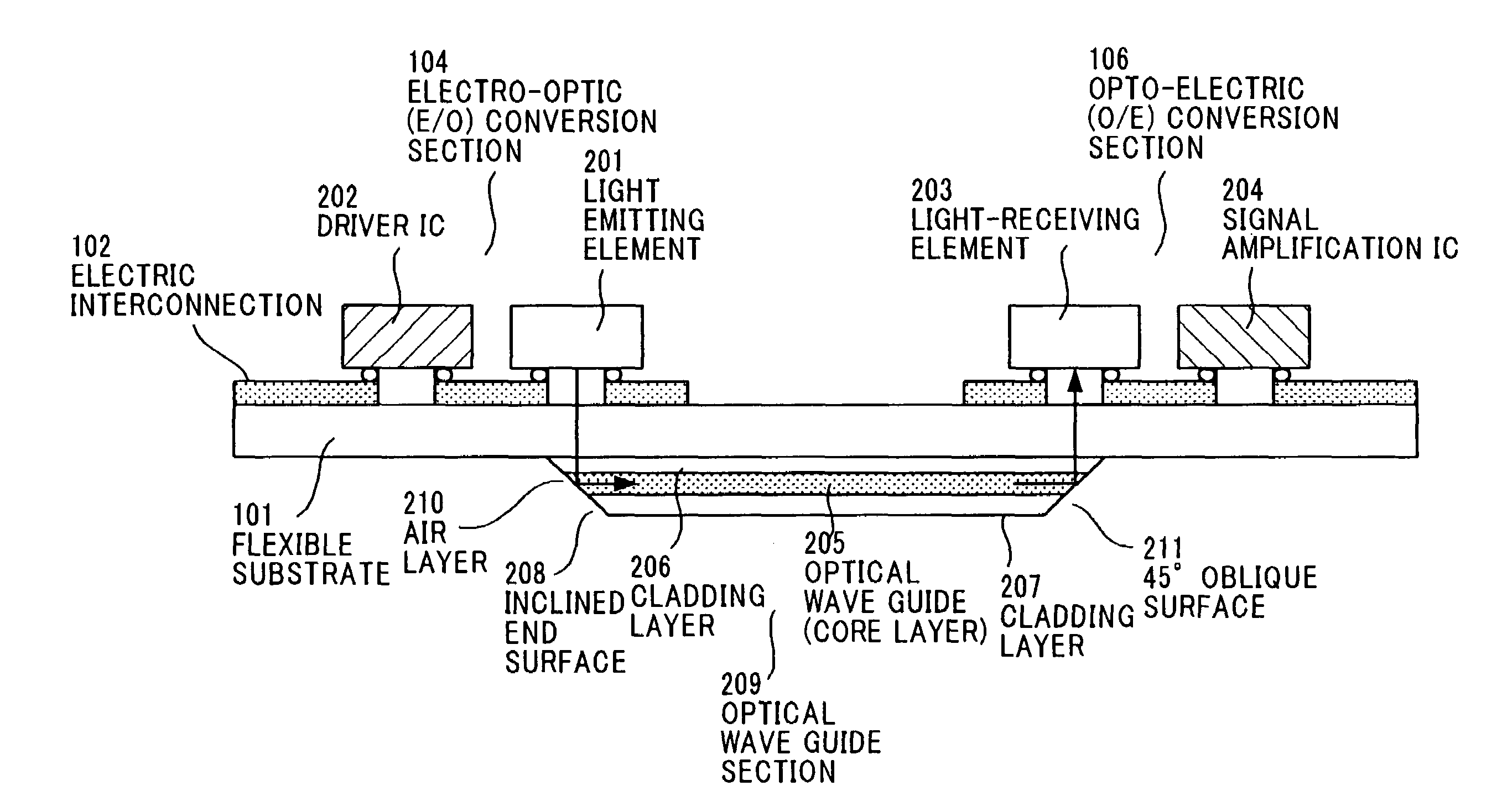
[0060]FIG. 5 is a top view showing the whole construction of a photoelectric composite interconnection assembly 100 of the invention, and FIG. 6A is a sectional view showing the photoelectric composite interconnection assembly 100 of the invention.

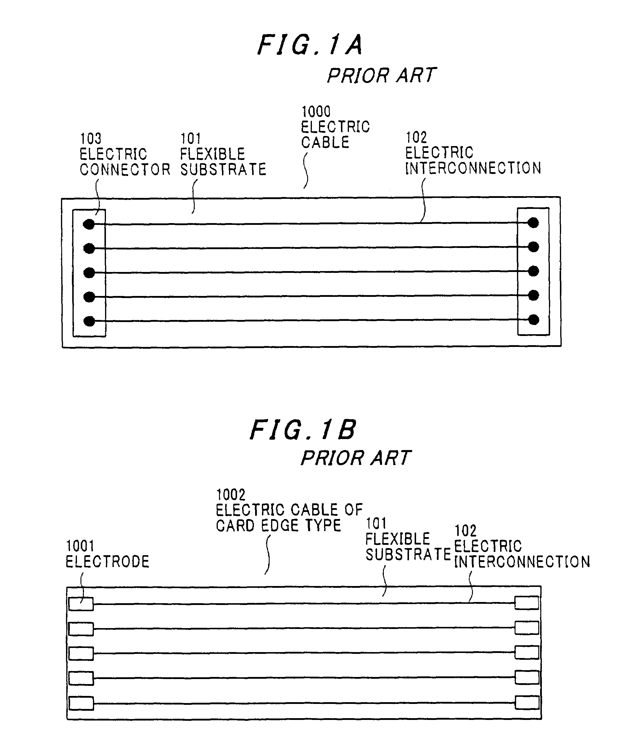
[0061]In the photoelectric composite interconnection assembly 100, electric interconnections 102 made of a copper material are provided on a flexible substrate 101 having flexibility and optical transparency, and electric connectors 103 each having a plurality of terminals are provided at both ends of the flexible substrate 101. The electric connector 103 interfaces in between respective electronic modules to transmit electrical signals between them. A polymer material is desirable as a material for the flexible substrate 101 having flexibility and optical transparency, and a specific example of the polymer material ...


PUM


Abstract

A photoelectric composite interconnection assembly having: a flexible substrate having an electric interconnection; and an electrical interface provided at both ends of the electric interconnection. A part of the electric interconnection is replaced by an optical transmission line.

Description

[0001]The present application is based on Japanese patent application No. 2004-274671, the entire contents of which are incorporated herein by reference.BACKGROUND OF THE INVENTION[0002]1. Field of the Invention[0003]This invention relates to a photoelectric composite interconnection assembly and, particularly, to a photoelectric composite interconnection assembly with flexibility, and further relates to an electronics device using the same.[0004]2. Description of the Related Art[0005]The developments of high-speed and high-capacity communication technology are actively advanced with expansion of services and applications for handling high-capacity data such as picture images in telecommunication equipment such as personal computers and cellular phones. Under the circumstances, the developments of interconnections that allow high-speed and high-capacity communications at a high density inside an electronics device or among electronics devices attract attention.[0006]A conventional e...

Claims


Application Information

Patent Timeline
Patent Type & Authority Patents(United States)
IPC IPC(8): G02B6/12
CPCG02B6/12004G02B6/1221G02B6/42G02B6/10G02B6/4214G02B2006/12104H01L2224/16225H01L2924/00014H01L2924/00011H01L2224/0401
Inventor KOBAYASHI, MASAHIKOHIRUTA, AKIHIRO
Owner HITACHI CABLE
Why Eureka
Try Eureka