Variable optical attenuator systems

a variable optical attenuator and optical switching technology, applied in the direction of optics, polarising elements, instruments, etc., can solve the problems of high manufacturing and assembly costs, inability to meet the needs of fixed (i.e., passive) attenuation devices, and reduced reliability and extreme sensitivity to alignmen

Inactive Publication Date: 2008-02-19
AVAGO TECH WIRELESS IP SINGAPORE PTE
View PDF7 Cites 67 Cited by
  • Summary
  • Abstract
  • Description
  • Claims
  • Application Information

AI Technical Summary

Benefits of technology

[0016]In one embodiment, a system of the present invention includes a polarization separating sub-system a polarization recombining sub-system and one or more switchable volume diffraction gratings to provide polarization insensitive low loss, reliable variable optical attenuators and 1×2 optical switches. The polarization separating sub-system is optically disposed to receive an input optical beam of arbitrary polarization and is also capable of separating the input optical beam into a first optical beam of a first polarization and a second optical beam of a second distinct, orthogonal polarization. The polarization separating sub-system is also capable of emitting a first emitted optical beam of the first polarization and a second emitted optical beam of the first polarization, the emitted first and emitted second optical beams constituting an input channel of the first polarization. The one or more switchable volume diffraction gratings are optically disposed to receive the input channel and are also capable of providing one or more transmitted channels. The one or more transmitted channels include at least one transmitted optical beam of the first polarization and at least one other transmitted optical beam of the first polarization. The polarization recombining sub-system is optically disposed to receive the at least one transmitted optical beam of the first polarization and the at least one other transmitted optical beam of the first polarization and is capable of recombining the at least one transmitted optical beam of the first polarization and the at least one other transmitted optical beam of the first polarization into at least one final output beam of combined polarization.

Problems solved by technology

A fixed (i.e., passive) attenuation device is impractical for this purpose.
Both of this type of attenuators exhibit a number of characteristics that are not desirable, such as high manufacturing and assembly costs, reduced reliability and extreme sensitivity to alignment.
A common problem encountered in applications in which high data rate information is modulated on optical carrier beams is the switching of the optical carriers from among an array of channels.
However, from noise, space, and cost perspectives it is sometimes more desirable to directly switch the route of the optical carrier from the input channel to the desired channel, without converting to and from the electronic (or microwave) regimes.
A problem that is typical in optical switching systems is the insertion loss they impose.
Others use switches that are inefficient and absorb, scatter, or divert a significant part of the input signal.

Method used


Image

  • Variable optical attenuator systems
  • Variable optical attenuator systems
  • Variable optical attenuator systems

Examples


Embodiment Construction

[0032]In order to better understand the present invention described below, it should be noted that certain terms used in the description of the invention have been used interchangeably.

[0033]In the following descriptions of the present invention, the terms such as “light” and “optical radiation” may be used interchangeably, and these terms both include electromagnetic radiation over the entire spectrum of wavelengths such as, for example, ultraviolet, visible, and infrared. Also, the term “optical”, for example, as applied to components and systems, refers not only to optical components and systems, but also to electro-optical components and systems.

[0034]Furthermore, terms such as “beams” and “channels” may also be interchanged, in certain instances, based upon their usage as recognized in the art.

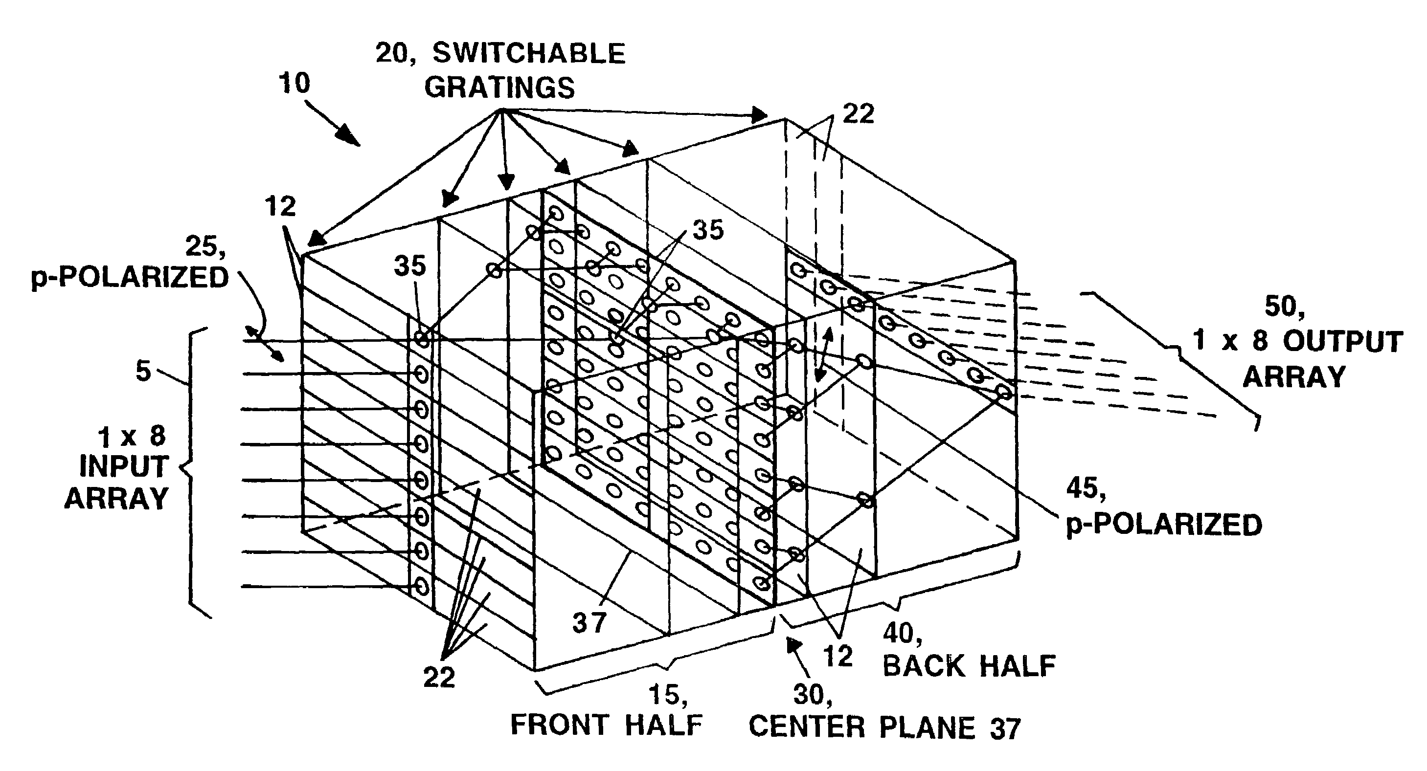
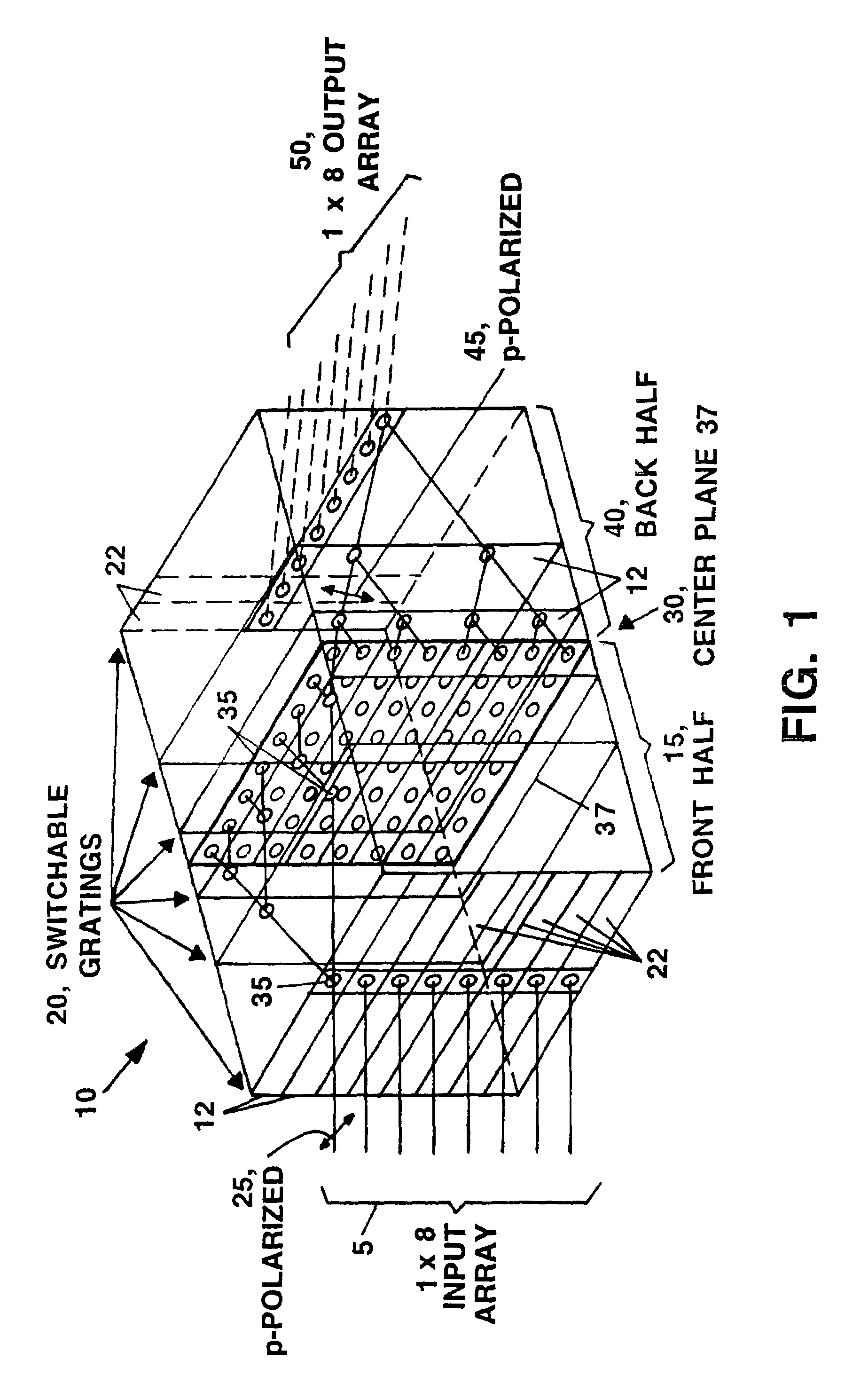
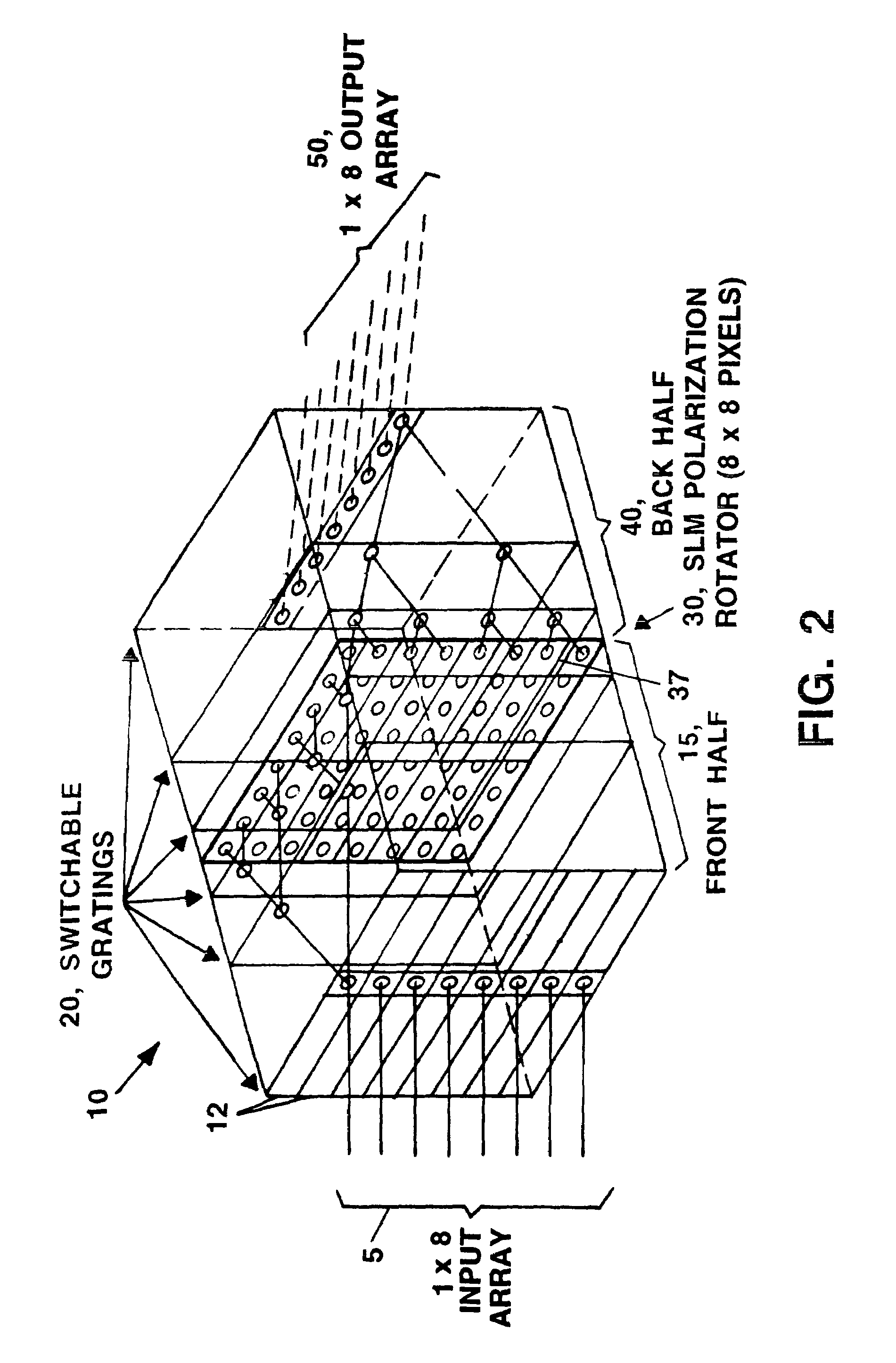
[0035]Low loss, reliable variable optical attenuators and 1×2 switches and polarization insensitive low loss, reliable variable optical attenuators and 1×2 optical switches are disclosed ...


PUM

PropertyMeasurementUnit
transmission volumeaaaaaaaaaa
transparentaaaaaaaaaa
photosensitiveaaaaaaaaaa

Abstract

Low loss, reliable variable optical attenuators and 1×2 switches and polarization insensitive low loss, reliable variable optical attenuators and 1×2 optical switches are described. In one embodiment, a system of the present invention includes a polarization separating sub-system a polarization recombining sub-system and one or more switchable volume diffraction gratings to provide polarization insensitive low loss, reliable variable optical attenuators and 1×2 optical switches.

Description

FIELD OF THE INVENTION[0001]The present invention relates generally to interconnection and switching systems, and, more particularly, to optical switching / routing (interconnecting) systems which incorporate the use of selectable switching and routing components.BACKGROUND OF THE INVENTION[0002]In many current and future systems light beams are modulated in a digital and / or analog fashion and are used as “optical carriers” of information. There are many reasons why light beams or optical carriers may be preferred in these applications. For example, as the data rate required of such channels increases, the high optical frequencies provide a tremendous improvement in available bandwidth over conventional electrical channels such as formed by wires and coaxial cables. In addition, the energy required to drive and carry high bandwidth signals can be reduced at optical frequencies. Furthermore, optical channels, even those propagating in free space (without waveguides such as optical fibe...

Claims


Application Information

Patent Timeline
Patent Type & Authority Patents(United States)
IPC IPC(8): G02B6/26G02B6/42G02B6/34G02B6/35G02F1/31
CPCG02B6/266G02B6/272G02F1/31G02B6/29311G02B6/29313G02B6/355G02B6/3592G02B6/3594G02F2201/305G02F2203/48
Inventor STONE, THOMAS W.KRALIK, JOHN C.
Owner AVAGO TECH WIRELESS IP SINGAPORE PTE
Why Eureka
Try Eureka