

Fiber optics transmission line
a fiber optics and transmission line technology, applied in the field of fiber optics transmission lines, can solve the problems of difficult to say that a satisfactory effect can be obtained, limit the range of core diameter that can be expanded, and so as to increase the size of the apparatus, complicate the manufacturing process, and increase the cost
- Summary
- Abstract
- Description
- Claims
- Application Information
AI Technical Summary
Benefits of technology
Problems solved by technology
Method used
Image

Examples
example 1
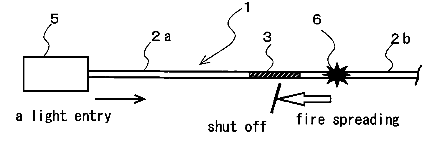
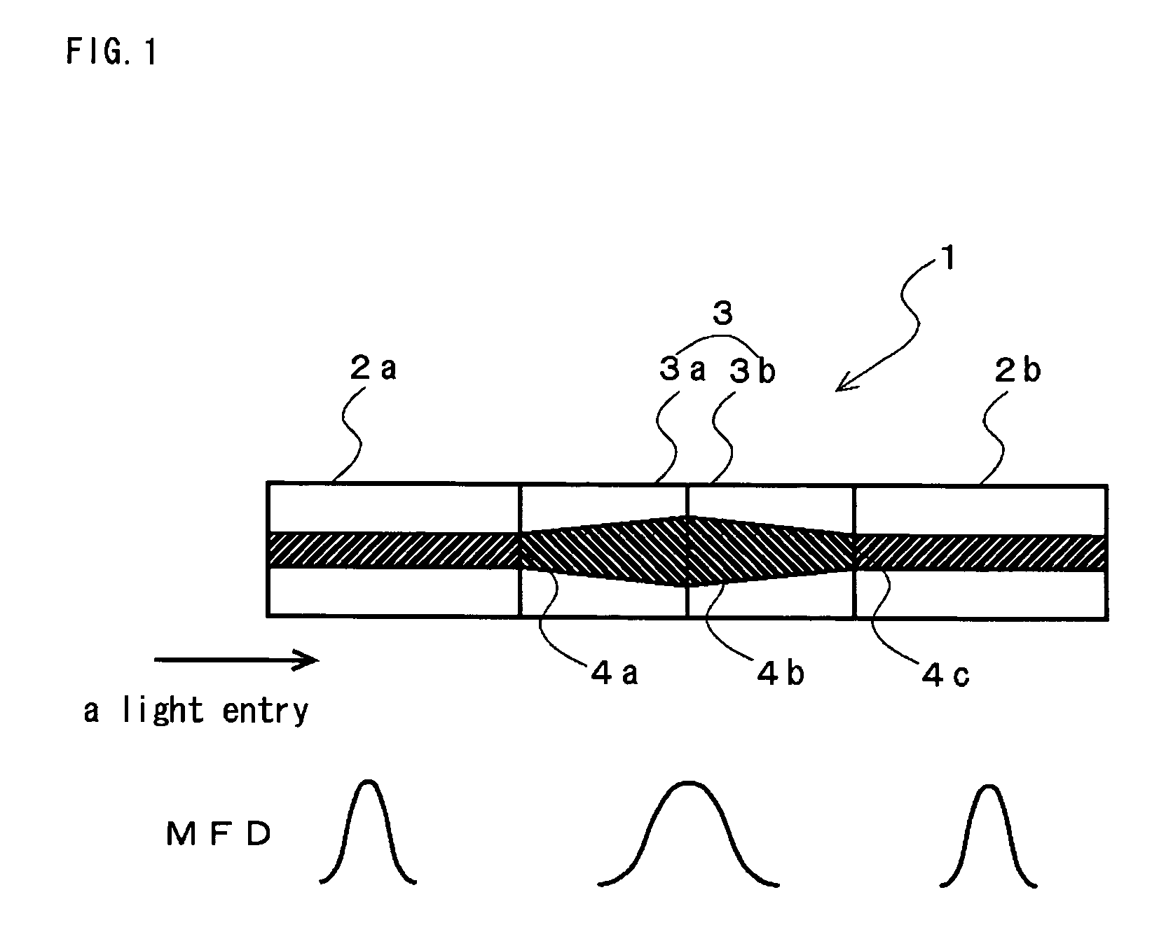
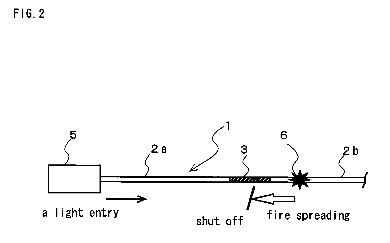
[0131]A fiber optics transmission line having the configuration shown in FIG. 1 was prepared, in which a GIF whose MFD was expanded up to 40 μm and core diameter set to 60 μm was inserted into a fiber optics. When an optical signal was transmitted from a Raman amplifier having a wavelength of 1550 nm and an optical power of 3 W into the fiber optics transmission line thus formed, fiber fuse phenomenon occurred. The MFD of a transmission-use SMF at this time was 10 μm. Although fire spreading toward a light source due to the fiber fuse phenomenon started, the fire spreading was shut off in the GIF.
[0132]The total connection loss between the transmission-use SMF 2a and GIF 3a, between GIF 3a and GIF 3b, and between GIF 3b and transmission-use SMF 2b obtained in a state where the fiber fuse phenomenon is absent was only 0.1 dB or less.
example 2
[0133]A fiber optics transmission line having the configuration shown in FIG. 5 was prepared, in which a GIF whose MFD was expanded up to 30 μm and core diameter set to 45 μm and an MFD-expanded SMF were inserted into a fiber optics. When an optical signal was transmitted from a YAG laser having a wavelength of 1050 nm and an optical power of 2 W into the fiber optics transmission line thus formed, fiber fuse phenomenon occurred. The MFD of a transmission-use SMF at this time was 8 μm. Although fire spreading toward a light source due to the fiber fuse phenomenon started, the fire spreading was shut off in the MFD-expanded SMF.
[0134]In this example, an NSP (Non-Strippable Primary Coating) SMF was used as a transmission-use SMF. This SMF and GIF were mechanical connected by a V-groove, and matching oil was applied to the fiber end face. The total connection loss between the transmission-use SMF 2a and GIF 3a, between GIF 3a and MFD-expanded SMF 7, between MFD-expanded SMF 7 and GIF 3...
example 3
[0135]A fiber optics transmission line having the configuration shown in FIG. 7 was prepared, in which a fiber-fuse phenomenon shut-off part constituted by a GIF whose MFD was expanded up to 50 μm and core diameter set to 100 μm and an MFD-expanded SMF was connected to one side optical switch, in place of an adapter and, similarly, another fiber-fuse phenomenon shut-off part constituted by a GIF whose MFD was expanded up to 50 μm and an MFD-expanded SMF was connected to the other side of the optical switch. When an optical signal was transmitted from a femtosecond laser having a wavelength of 1550 nm and an optical power of 4 W into the fiber optics transmission line thus formed, fiber fuse phenomenon occurred. The MFD of a transmission-use SMF at this time was 7.5 μm. Although fire spreading toward a light source due to the fiber fuse phenomenon started, the fire spreading was shut off in front of the optical switch.
[0136]The total connection loss between the transmission-use SMF 2...
PUM
 Abstract
Description
Claims
Application Information