Control apparatus for internal combustion engine

a control apparatus and internal combustion engine technology, applied in the direction of electric control, combustion engines, machines/engines, etc., can solve the problems of inefficient time and/or response, delay in response, and oxygen amount, and achieve the effect of favorable respons

Inactive Publication Date: 2008-02-26
TOYOTA JIDOSHA KK
View PDF23 Cites 18 Cited by
  • Summary
  • Abstract
  • Description
  • Claims
  • Application Information

AI Technical Summary

Benefits of technology

[0013]An object of the present invention is to provide a control apparatus for an internal combustion engine that includes a first fuel injection mechanism for injecting fuel towards a cylinder and a second fuel injection mechanism for injecting fuel towards the intake manifold or an intake port, allowing air-fuel ratio feedback control of favorable response.
[0015]In the execution of feedback control involving a proportional action corresponding to multiplying the difference between a target air-fuel ratio and sensed air-fuel ratio by a proportional gain, only the quantity of fuel injected by the first fuel injection mechanism that injects fuel into a cylinder (for example, in-cylinder injector) is taken as the control input of the feedback system in the proportional action. Although the second fuel injection mechanism injecting fuel into an intake manifold (for example, an intake manifold injector) causes delay time due to the injected fuel adhering to the wall of the intake manifold and the distance up to the combustion chamber, the in-cylinder injector is absent of such delay time, allowing a high gain to be set in the proportional action of feedback control. Accordingly, the response in feedback control can be improved. Thus, a control apparatus for an internal combustion engine including a first fuel injection mechanism injecting fuel towards a cylinder and a second fuel injection mechanism injecting fuel towards the intake manifold or intake port, allowing air-fuel ratio feedback control of favorable response can be provided.
[0017]In addition to the proportional action in the feedback control system of the present invention, an integral action to eliminate the steady state deviation or a derivative action to compensate for the integral action to improve control stability may be added. Since the fuel injection ratio between the in-cylinder injector and the intake manifold injector is set based on the operation state of the internal combustion engine in addition to such air-fuel ratio feedback control, the fuel injection ratio will deviate from the injection ratio calculated from the operation state of the internal combustion engine if only the quantity of fuel injected from the intake manifold injector is employed for the control input in the air-fuel ratio feedback control. In view of this issue, the control input of the feedback system in the integral action is reflected in the fuel injection quantity of the intake manifold injector, whereas the control input of the feedback system in the proportional action and derivative action is reflected in only the fuel injection quantity of the in-cylinder injector. Since the delay time caused by the fuel injected from the intake manifold injector adhering on the wall does not affect the integral action, a feedback control system of favorable response and of no steady state deviation can be realized while obviating significant deviation from the fuel injection ratio of the in-cylinder injector to the intake manifold injector that is calculated based on the operation state of the internal combustion engine. Thus, a control apparatus for an internal combustion engine including a first fuel injection mechanism injecting fuel towards a cylinder and a second fuel injection mechanism injecting fuel towards the intake manifold or intake port, allowing stable air-fuel ratio feedback control of favorable response and of no steady state deviation can be provided.
[0019]In addition to the proportional action in the feedback control system of the present invention, an integral action to eliminate steady state deviation may be added. Since the fuel injection ratio between the in-cylinder injector and the intake manifold injector is set based on the operation state of the internal combustion engine in addition to such air-fuel ratio feedback control, the fuel injection ratio will deviate from the injection ratio calculated from the operation state of the internal combustion engine if only the quantity of fuel injected from the intake manifold injector is employed for the control input in the air-fuel ratio feedback control. In view of the foregoing, the control input of the feedback system in the integral action is reflected in the fuel injection quantity of the intake manifold injector, whereas the control input of the feedback system in the proportional action is reflected in only the fuel injection quantity of the in-cylinder injector. Since the delay time caused by the fuel injected from the intake manifold injector adhering on the wall does not affect the integral action, a feedback control system of favorable response can be realized while obviating significant deviation from the fuel injection ratio of the in-cylinder injector to the intake manifold injector that is calculated based on the operation state of the internal combustion engine. Thus, a control apparatus for an internal combustion engine including a first fuel injection mechanism injecting fuel towards a cylinder and a second fuel injection mechanism injecting fuel towards the intake manifold or intake port, allowing air-fuel ratio feedback control of favorable response and of no steady state deviation can be provided.
[0023]In accordance with the present invention, there can be provided a control apparatus for an internal combustion engine that includes an in-cylinder injector as the first fuel injection mechanism and an intake manifold injector as the second fuel injection mechanism, partaking in fuel injection, and allowing air-fuel ratio feedback control of favorable response.

Problems solved by technology

This is because all these three noxious components set forth above cannot be purified favorably since oxidation is active whereas reduction is inactive when the air-fuel ratio is lean and the amount of oxygen in the exhaust gas is high, and the reduction is active whereas oxidization is inactive when the air-fuel ratio is rich and the amount of oxygen in the exhaust gas is low.
Although the convergence towards a target value is accelerated as the gain of feedback control becomes higher, there is the possibility of oscillation when the gain is too high.
This gain depends upon the inefficient time and / or delay in response of the control system.
The fuel injected from the intake manifold injector will adhere to the inner wall of the intake manifold, causing delay in response.
It was therefore difficult to increase the response to the target value.
The tendency of causing delay in response due to the wall adherence of fuel injected from the intake manifold injector becomes more significant as the intake manifold is under a cold state.
This means that, even if the amount of fuel injected from the intake manifold injector is increased to achieve a rich state from the lean state, a high gain cannot be set since the delay is serious due to the effect of adherence at the wall when the temperature is low.
Thus, favorable response could not be realized.

Method used


Image

  • Control apparatus for internal combustion engine
  • Control apparatus for internal combustion engine
  • Control apparatus for internal combustion engine

Examples


Embodiment Construction

[0034]Embodiments of the present invention will be described hereinafter with reference to the drawings. The same components have the same reference characters allotted, and their designation and function are also identical. Therefore, detailed description thereof will not be repeated.

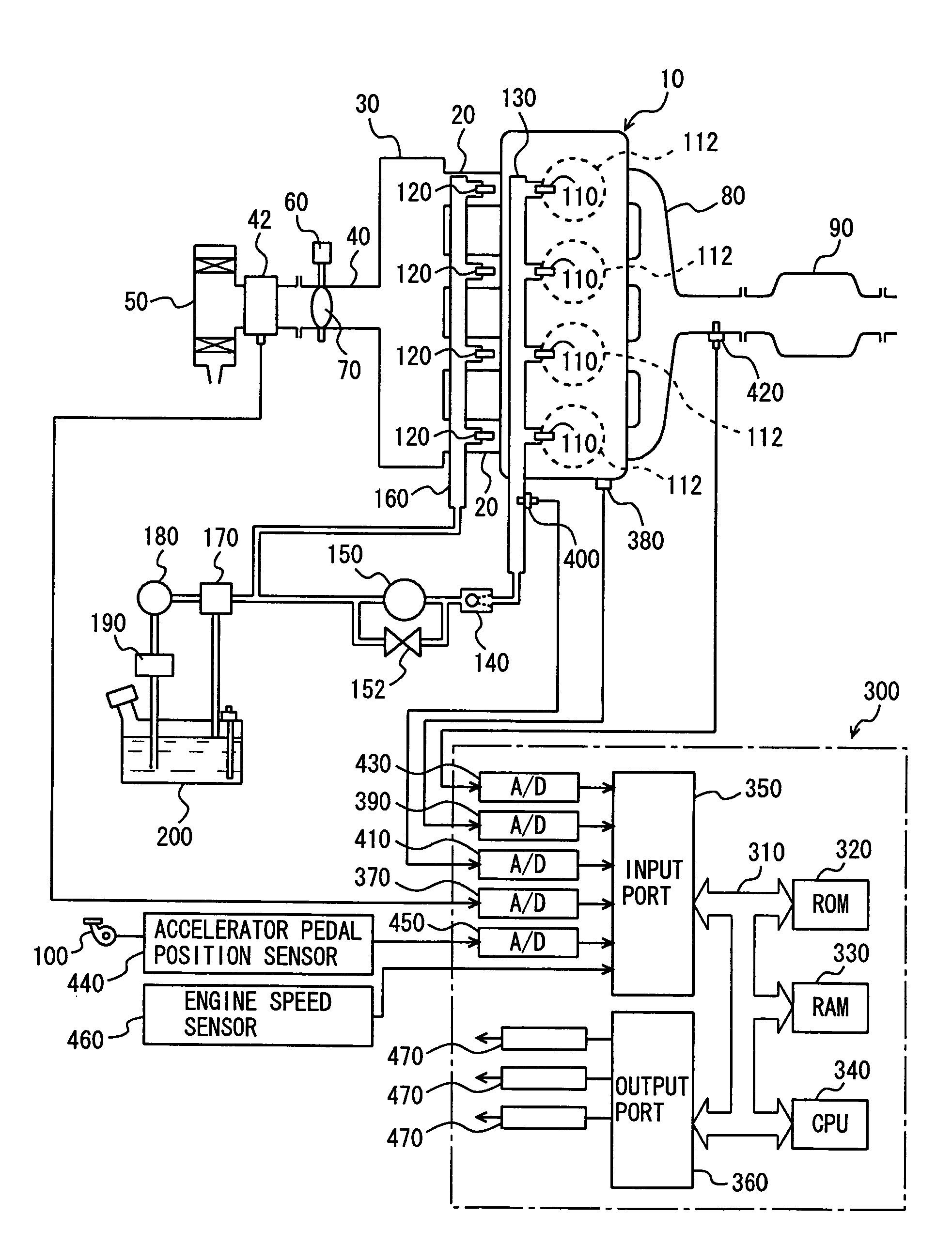
[0035]FIG. 1 is a schematic view of a structure of an engine system under control of an engine ECU (Electronic Control Unit) identified as a control apparatus for an internal combustion engine according to an embodiment of the present invention. Although an in-line 4-cylinder gasoline engine is indicated as the engine, the present invention is not limited to such an engine.

[0036]As shown in FIG. 1, the engine 10 includes four cylinders 112, each connected to a common surge tank 30 via a corresponding intake manifold 20. Surge tank 30 is connected via an intake duct 40 to an air cleaner 50. An airflow meter 42 is arranged in intake duct 40, and a throttle valve 70 driven by an electric motor 60 is also ...


PUM


Abstract

An air-fuel ratio feedback system is configured to calculate the deviation between a target air-fuel ratio and an air-fuel ratio sensor value, multiplying a proportional gain by the calculated deviation to obtain a feedback correction value, and add the calculated feedback correction value to the in-cylinder injection quantity of an in-cylinder injector that is obtained by multiplying the fuel injection ratio of the in-cylinder injector by the basic fuel injection quantity. The calculated feedback correction value is not added to the port injection quantity of the intake manifold cylinder.

Description

[0001]This nonprovisional application is based on Japanese Patent Application No. 2005-078287 filed with the Japan Patent Office on Mar. 18, 2005, the entire contents of which are hereby incorporated by reference.BACKGROUND OF THE INVENTION[0002]1. Field of the Invention[0003]The present invention relates to a control apparatus for an internal combustion engine including a first fuel injection mechanism (in-cylinder injector) injecting fuel into a cylinder and a second fuel injection mechanism (intake manifold injector) injecting fuel towards an intake manifold or an intake port, and particularly to a control apparatus for feedback control of the air-fuel ratio of the exhaust system prior to the catalyst to the stoichiometric air-fuel ratio.[0004]2. Description of the Background Art[0005]An internal combustion engine is well-known, including an intake manifold injector for injecting fuel into the intake manifold of the engine and an in-cylinder injector for injecting fuel into the e...

Claims


Application Information

Patent Timeline
Patent Type & Authority Patents(United States)
IPC IPC(8): F02B7/00F02B7/04
CPCF02D41/14F02D41/30F02D41/1482F02D41/1483F02D41/3094
Inventor KOBAYASHI, DAISUKE
Owner TOYOTA JIDOSHA KK
Why Eureka
Try Eureka