
Osmotically-driven fluid dispenser

a technology of fluid dispenser and motor, which is applied in the direction of packaging foodstuffs, packaged goods types, pharmaceutical containers, etc., can solve the problems of reducing the performance or complete failure of the pump, affecting the performance of the pump, and affecting the coating composition, so as to improve the performance of the mini-osmotic pump and improve the coating composition

Inactive Publication Date: 2008-02-26
DURECT CORP
View PDF53 Cites 6 Cited by
  • Summary
  • Abstract
  • Description
  • Claims
  • Application Information

AI Technical Summary

Benefits of technology

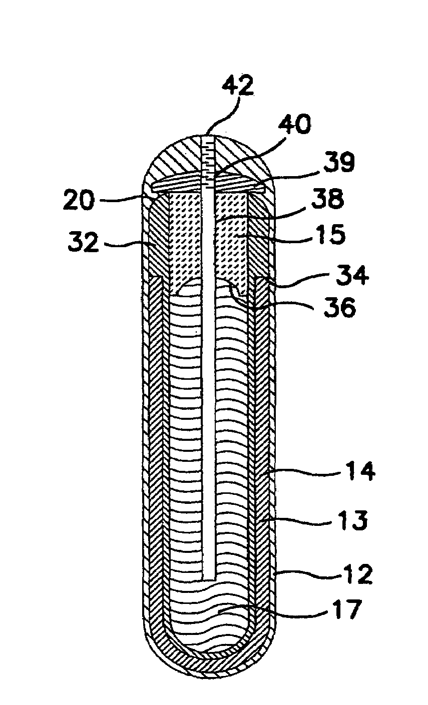
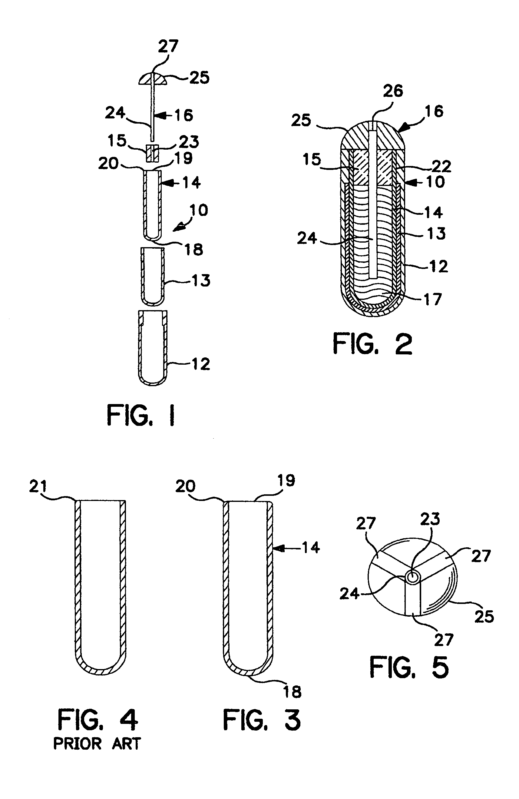
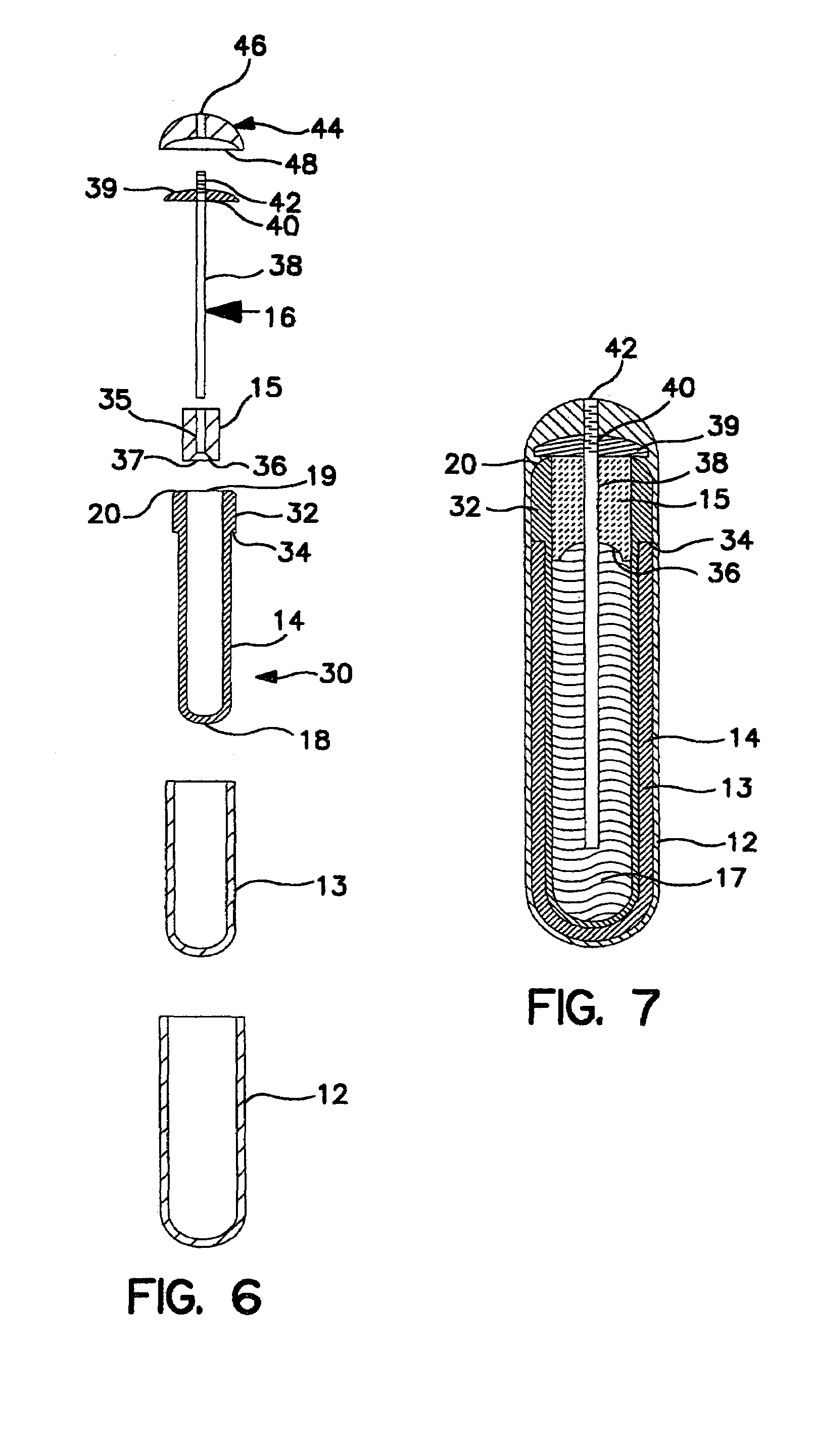
The invention is an improvement to a mini-osmotic pump that can dispense fluids. The improvement includes a modified inner bag with an arcuate edge, an intermediate layer of osmotically effective solute composition, and an outer, shape-retaining membrane that is at least partially permeable to water. The membrane is made from a coating composition that includes a mixture of polymer and solvent. The coating composition can form a semipermeable membrane with a water transmission rate of between 1-60 cc·mil / cm2·hr. The technical effects of the invention include improved pump efficiency, reduced membrane thickness, and improved fluid dispensing accuracy.

Problems solved by technology

One shortcoming of the above-described pumps is the tendency to develop cracks in the region of the seal between the inner bag and the outer membrane.
Formation of fissures in the outer membrane in the region of the joint between the open end of the inner bag results in decreased performance or complete failure of the pump, evidenced by a decreased or non-constant flow rate or an absence of flow.

Method used


Image

  • Osmotically-driven fluid dispenser
  • Osmotically-driven fluid dispenser
  • Osmotically-driven fluid dispenser

Examples


example 1

[0049]Cylindrical flexible bags (2.50 cm long, 4.01 mm I.D. and 4.62 mm O.D.) were injection molded at 176° C., 3.5.times.103 kPa, from an elastomeric styrene-butadiene copolymer (sold under the trade designation, KRATON 2104). The mold was designed to form bags having an arcuate edge with a radius of curvature of 0.047 inches at the open end of each bag.

[0050]Osmotic sleeves were prepared for each dispenser as follows. The components 64.5 wt % NaCl, 20 w % poly[ethylene oxide], molecular wt 600,000, 15 wt % poly[ethylene glycol] of molecular weight 20,000 and 0.5 wt % colloidal SiO2, sold under the trade name CABOSIL were bulk blended in a Hobart mixer for 20 minutes at low speed. The homogenous powder blend was pressed into 0.6 cm tablets capable of being gravity fed into Arborg injection molding equipment. The osmotic sleeves (2.21 cm long, 4.87 mm I.D., and 5.89 mm O.D.) were formed from the tablets by injection molding at 149° C. 6.5.times.103 kPa.

[0051]Cylindrical plugs of KRA...

example 2

[0056]The foregoing procedure is repeated using cellulose acetate propionate as the polymer. Release profiles for the dispenser are satisfactory and the absence of cracks in the seal region is noted.

example 3

[0057]The acetone in the coating solution of Example 1 is replaced with equivalent quantities of acetone-water (90:10), acetone-methanol (90:10), and acetone-ethanol (90:10), and the procedures of the Example repeated in other respects. Devices prepared therefrom are satisfactory and the absence of cracks in the seal region is noted.


PUM

PropertyMeasurementUnit
90° angleaaaaaaaaaa
angleaaaaaaaaaa
viscositiesaaaaaaaaaa

Abstract

Improvements in a mini-osmotic pump and coating compositions are described. The dispensing pump includes an inner fluid-filled bag encased by an osmotic layer and outer, semi-permeable membrane. The inner bag is formed with an arcuate edge at the open end of the bag to inhibit formation of fissures in the outer membrane in this edge region. The coating compositions include cellulose acetate butyrate, cellulose acetate propionate, and polymethylmethacrylate polymers, optionally mixed with ethyl cellulose in acetone based solvent systems.

Description

CROSS-REFERENCE TO RELATED APPLICATIONS [0001]“This application claims the priority of U.S. Provisional Application Ser. No. 60 / 180,395, filed Feb. 4, 2000, which is incorporated herein by reference. This application is also a divisional of application Ser. No. 09 / 772,815, filed Jan. 30, 2001, which is now abandoned.”BACKGROUND OF INVENTION [0002]1. Field of the Invention[0003]The present invention relates to improvements and modifications of an osmotically driven fluid dispenser and coating compositions for osmotically driven dispensers.[0004]2. Description of the Related Art[0005]Osmotically driven dispensers are described in commonly owned U.S. Pat. Nos. 3,760,984 and 4,320,758, which are hereby incorporated by reference in their entirety. The mini-osmotic pumps described in these patents as well as in the present invention are osmotically driven dispensers sized for use as therapeutic systems for administering drugs to animals and humans. The basic components of the pumps are an...

Claims


Application Information

Patent Timeline
Patent Type & Authority Patents(United States)
IPC IPC(8): A61K9/22A61J1/10A61K9/00A61K9/28A61K47/32A61K47/38A61M31/00
CPCA61K9/0004A61K9/2846A61K9/2866A61K9/20
Inventor WONG, PATRICK S. L.DAVAR, NIPUN
Owner DURECT CORP
Learn More