
Interface and process for enhanced transmission of non-circular ion beams between stages at unequal pressure

a technology of interfacial ion beam and non-circular ion beam, which is applied in the direction of separation process, particle separator tube details, instruments, etc., can solve the problems of less effective round jet disrupters, achieve normal enhanced ion funnel performance, maximize overlap, and reduce chemical noise

Inactive Publication Date: 2008-03-04
BATTELLE MEMORIAL INST
View PDF13 Cites 20 Cited by
  • Summary
  • Abstract
  • Description
  • Claims
  • Application Information

AI Technical Summary

Benefits of technology

The invention is about improving the transmission of non-circular ion beams between two instrument stages for analysis, characterization, separation, and generation of gas-phase ions with different gas pressures. This is achieved by providing a non-circular conductance limit aperture with the highest possible overlap with the cross-section of the ion beam to be transmitted, within the constraint of maximum aperture area allowing one to maintain the desired pressure differential between the stages. The non-circular aperture can be either contiguous or non-contiguous. The invention also provides an electrodynamic ion funnel with a sufficient entrance orifice installed behind the non-circular aperture and a non-circular jet disrupter to remove gas jets carrying incompletely desolvated microdroplets, solvent / matrix clusters, and other contaminants. The non-circular jet disrupter is designed to maximize the overlap with a non-circular gas jet.

Problems solved by technology

Non-circular inlets would produce non-circular jets for which a round jet disrupter may be less effective.

Method used


Image

  • Interface and process for enhanced transmission of non-circular ion beams between stages at unequal pressure
  • Interface and process for enhanced transmission of non-circular ion beams between stages at unequal pressure
  • Interface and process for enhanced transmission of non-circular ion beams between stages at unequal pressure

Examples


example 1

Demonstration of Non-Circular Aperture Interface

[0039]The invention has been demonstrated in a system 500 comprising three stages: a custom-built p-FAIMS 530 illustrated in FIG. 5 and FIG. 7, a drift tube 540, and a time-of-flight MS (Sciex Q-Star ToF MS) 550.

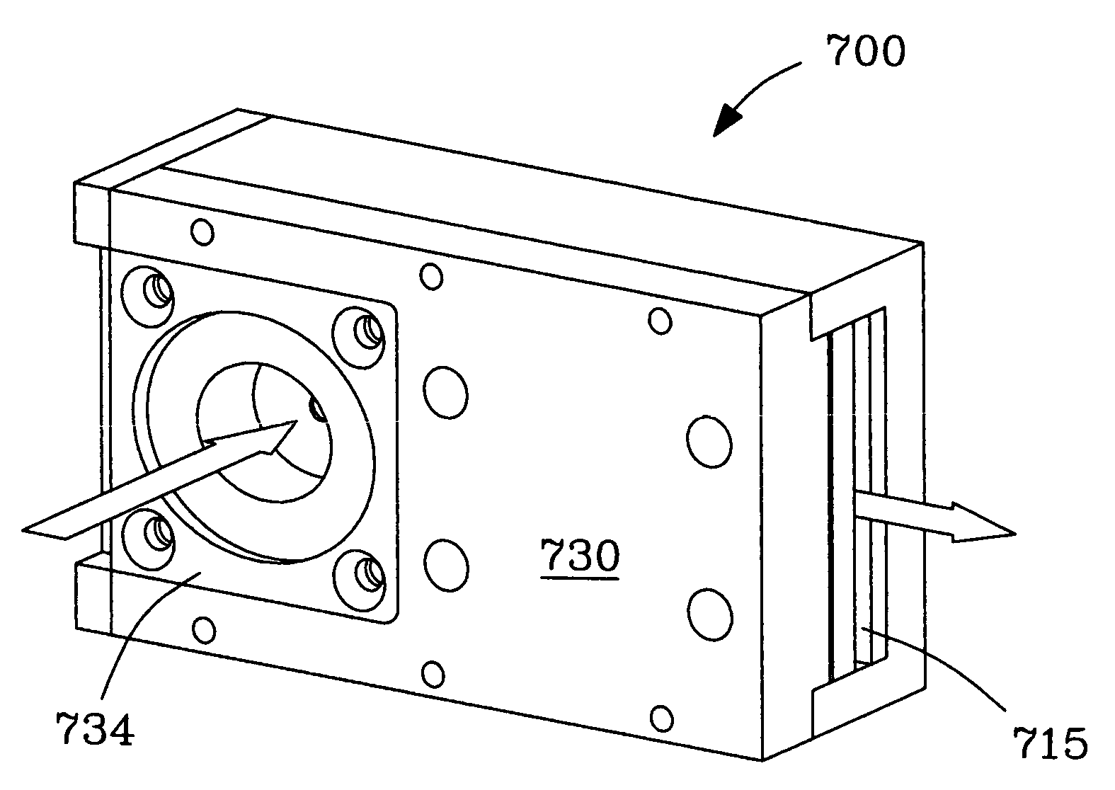
[0040]Experimental. A FAIMS stage 530 was coupled to a drift tube 540 and MS stage 550 as shown in FIG. 5, using a 25-mm “hourglass” ion funnel 520, e.g., as described by Smith et al. (U.S. Pat. No. 6,818,890, U.S. Pat. No. 6,967,325) incorporated herein in their entirety. Drift tube 540 was operated in the “continuous mode”, i.e., with no mobility separation. Dimensions of the FAIMS 530 analytical gap were: width=2 mm, span=20 mm, length ˜30 mm. Ion source 560 was an ESI source. Carrier gas was nitrogen (N2) gas at ambient conditions, with the total flow of 2 L / min partitioned between the curtain gas desolvating ions at the ESI / FAIMS interface and carrier gas moving ions through FAIMS. FIG. 7 presents an end-on view 700 (with ...

example 2

Instrumental Sensitivity Using a Non-Circular Aperture Interface

[0041]Example 2 demonstrates the sensitivity improvement provided by the use of a non-circular aperture 515 described herein.

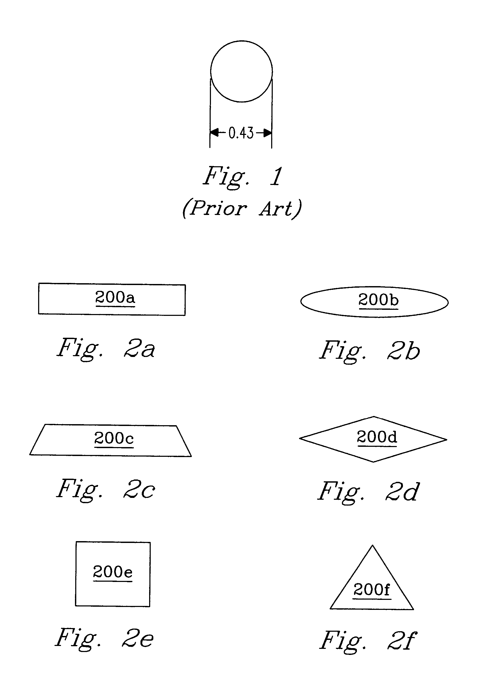
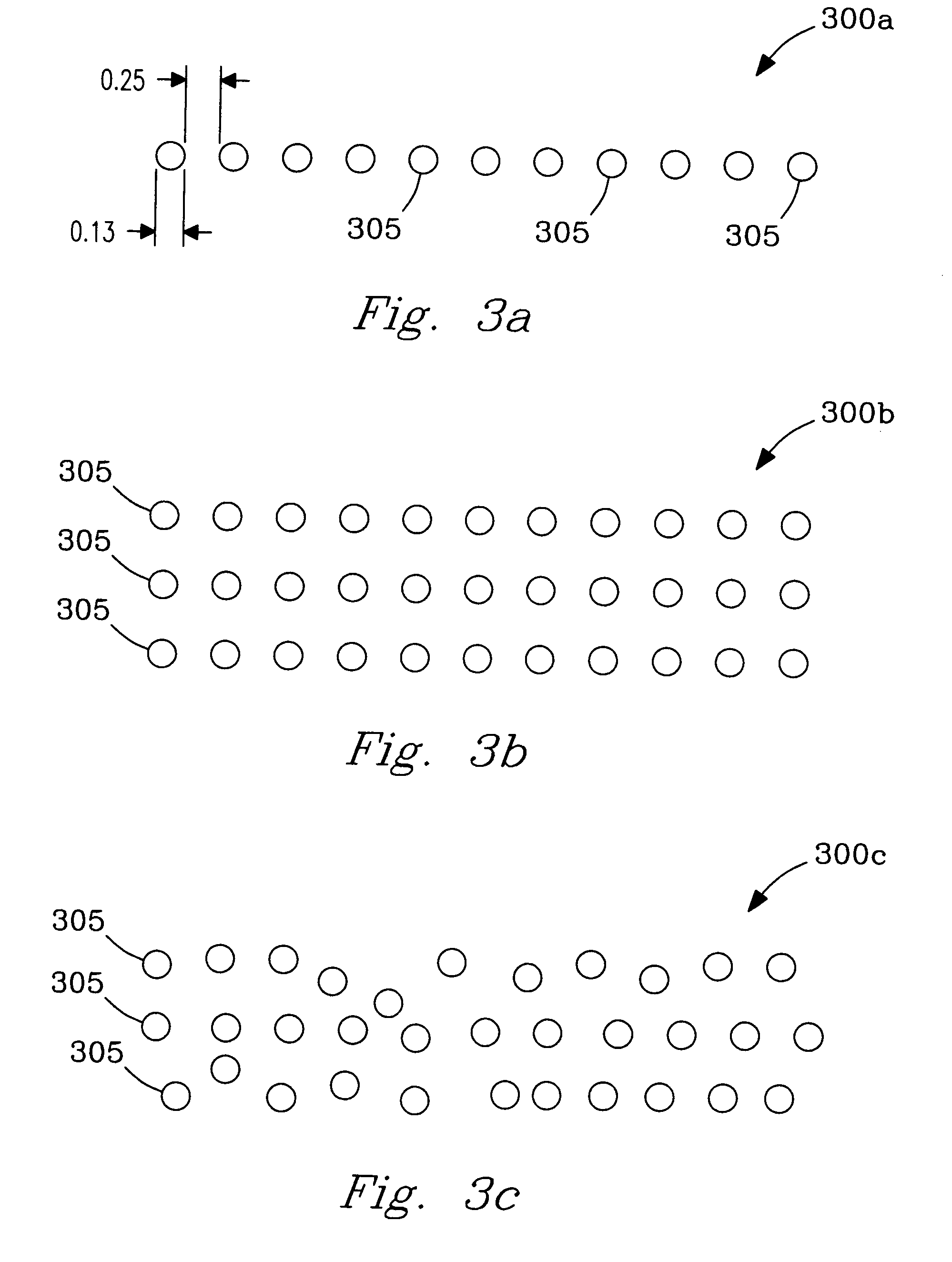
[0042]Experimental. The improvement of analytical sensitivity provided by a non-circular aperture 515 was evaluated by benchmarking vs. an otherwise identical interface with a conventional round aperture, with all other instrument parameters kept constant. In the exemplary embodiment, described herein with reference to FIG. 5 and FIG. 3a, the non-circular aperture 515 is non-contiguous, consisting of 11 circular apertures 305 of 0.13 mm diameter, uniformly disposed along a 3.8 mm-long straight segment, for a total area of ˜0.14 mm2. The benchmark aperture (illustrated in FIG. 1) is a contiguous circle of 0.43 mm diameter with the same area of ˜0.14 mm2. Both apertures are manufactured out of 0.4 mm-thick metal sheet and are not heated.

[0043]Results. Performance was evaluated for a protonated reser...


PUM


Abstract

The invention discloses a new interface with non-circular conductance limit aperture(s) useful for effective transmission of non-circular ion beams between stages with different gas pressure. In particular, the invention provides an improved coupling of field asymmetric waveform ion mobility spectrometry (FAIMS) analyzers of planar or side-to-side geometry to downstream stages such as mass spectrometry or ion mobility spectrometry. In this case, the non-circular aperture is rectangular; other geometries may be optimum in other applications. In the preferred embodiment, the non-circular aperture interface is followed by an electrodynamic ion funnel that may focus wide ion beams of any shape into tight circular beams with virtually no losses. The jet disrupter element of the funnel may also have a non-circular geometry, matching the shape of arriving ion beam. The improved sensitivity of planar FAIMS / MS has been demonstrated in experiments using a non-contiguous elongated aperture but other embodiments (e.g., with a contiguous slit aperture) may be preferable, especially in conjunction with an ion funnel operated at high pressures.

Description

[0001]This invention was made with Government support under Contract DE-AC05-76RLO1830 awarded by the U.S. Department of Energy. The Government has certain rights in the invention.FIELD OF THE INVENTION[0002]The present invention relates generally to instrumentation and methods for guidance and focusing of ions in the gas phase. More particularly, the invention relates to interfaces for ion transmission between coupled stages for analysis, characterization, separation, and / or generation of ions at different gas pressures.BACKGROUND OF THE INVENTION[0003]Field asymmetric waveform ion mobility spectrometry (FAIMS) is gaining broad acceptance as a post-ionization separation method coupled to mass spectrometry (MS), e.g., as reviewed by Guevremont (J. Chromatogr. A 2004, 1058, 3). Unlike conventional ion mobility spectrometry (IMS) based on the absolute ion mobilities (K), FAIMS separates ions by the difference between K in a particular gas at high and low electric fields (E). In practi...

Claims


Application Information

Patent Timeline
Patent Type & Authority Patents(United States)
IPC IPC(8): H01J49/06
CPCH01J49/067
Inventor TANG, KEQISHVARTSBURG, ALEXANDRE A.SMITH, RICHARD D.
Owner BATTELLE MEMORIAL INST
Learn More