
Phased array terminal for equatorial satellite constellations

a phased array and constellation technology, applied in the field of phased array antennas, can solve the problems of inacceptable consumers, high cost and bulky antennas with this current technology, and conventional tracking phased arrays are too expensive for a consumer market, and achieve low cost and low profile

Inactive Publication Date: 2008-03-04
HUGHES ELECTRONICS
View PDF69 Cites 41 Cited by
  • Summary
  • Abstract
  • Description
  • Claims
  • Application Information

AI Technical Summary

Benefits of technology

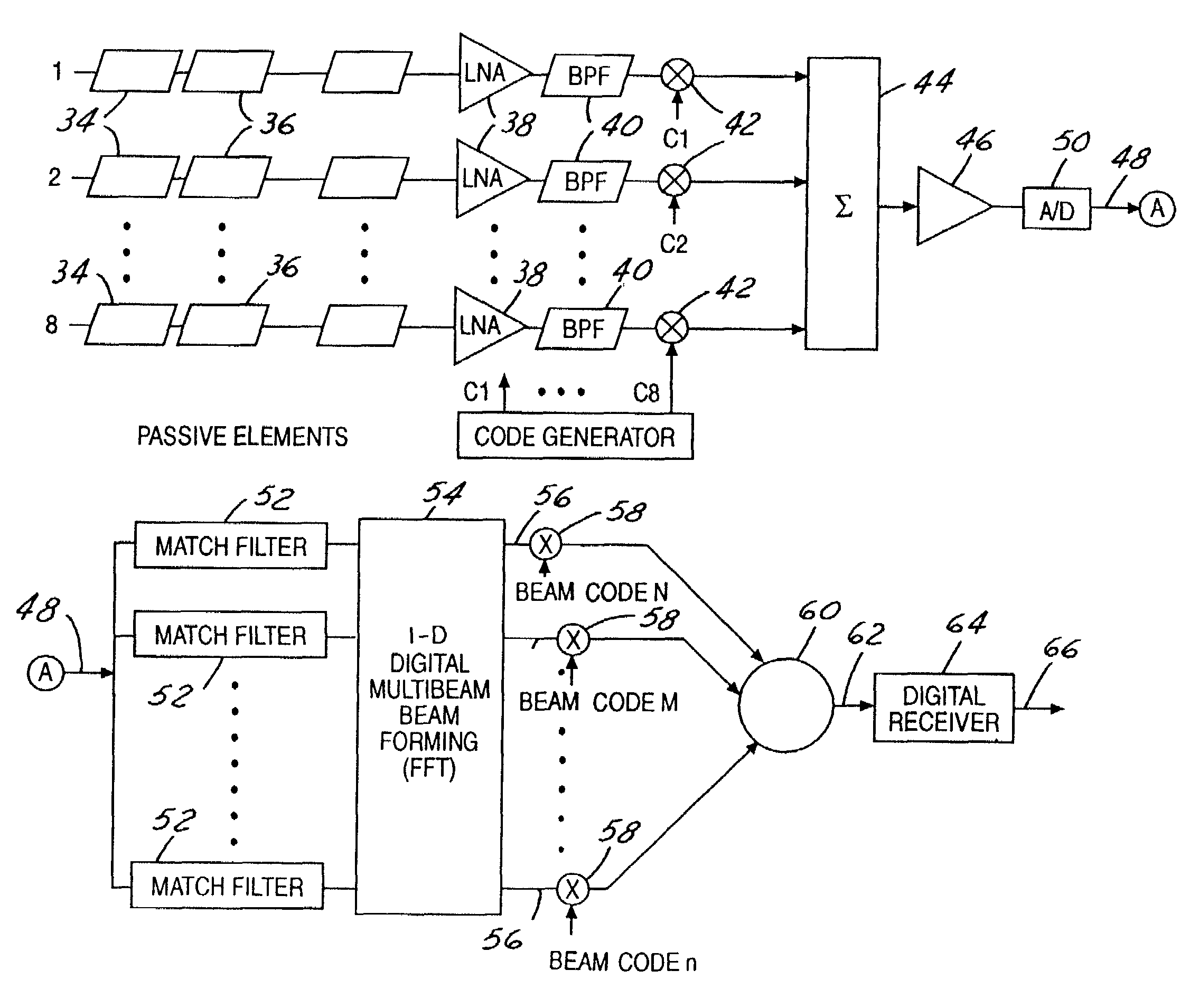
"The present invention provides a low profile multiple beam tracking phased array antenna for use on commercial equatorial satellite constellations. The antenna has a low profile, is relatively inexpensive, and provides high performance. It includes a rotating circular plate for scanning in the azimuth direction and a plurality of radiation elements that electronically scan in elevation. The antenna can receive multiple waves and multiplex them into a single analog signal before converting it to a digital bit stream. The digital bit stream is then transformed into multiple digital beam forms using a device that provides retrodirectivity. The technical effects of the invention include improved signal quality, reduced interference, and improved data transmission and processing."

Problems solved by technology

However, the tracking antennas with this current technology are expensive and bulky and, therefore, generally unacceptable to consumers.
These conventional tracking phased arrays are too expensive for a consumer market, primarily because each beam must have a separate set of electronics associated with each element to process the various signals, including many phase shifters and many duplicate strings of electronics.
Therefore, the manufacturing costs for these conventional tracking phased arrays are generally beyond that practical for the consumer market whether for use as a fixed antenna or by a user as a mobile antenna.
To provide a conventional tracking phased array that could be constructed with an acceptable profile, would be prohibitive in cost.
Further, these small tracking parabolic reflectors are not a viable alternative for a mobile user because of both their size and cost.

Method used


Image

  • Phased array terminal for equatorial satellite constellations
  • Phased array terminal for equatorial satellite constellations
  • Phased array terminal for equatorial satellite constellations

Examples


Embodiment Construction

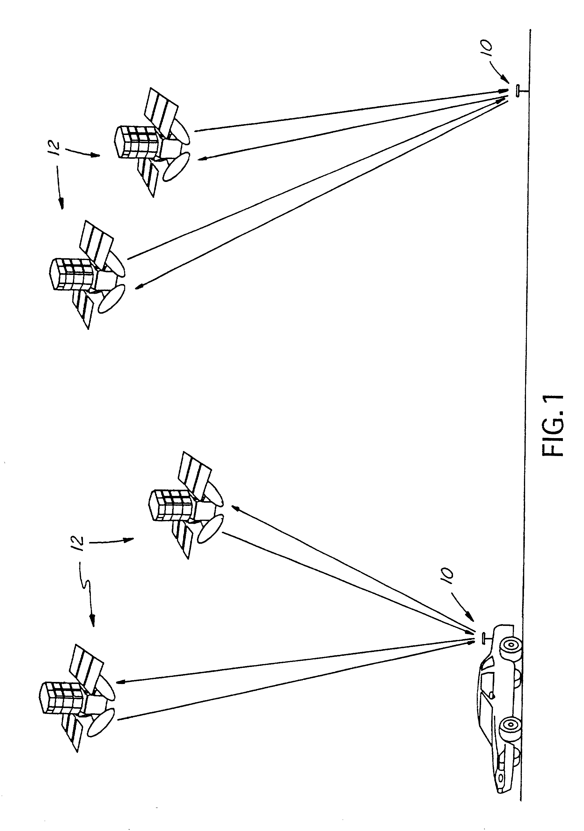
[0018]FIG. 1 illustrates an environmental view of the disclosed antenna in accordance with a preferred embodiment of the present invention. As shown, a preferred antenna 10 is positioned in a fixed position on the ground and is in communication with a plurality of orbiting satellites 12 to transmit signals thereto and receive signals therefrom. Another antenna 10 is attached to an automobile travelling along the ground which is also in communication with a plurality of orbiting satellites 12 to transmit signals thereto and receive signals therefrom. The disclosed antenna may also be attached to other mobile vehicles such as aircraft or boats. The satellites 12 are preferably medium earth orbit equatorial satellites.

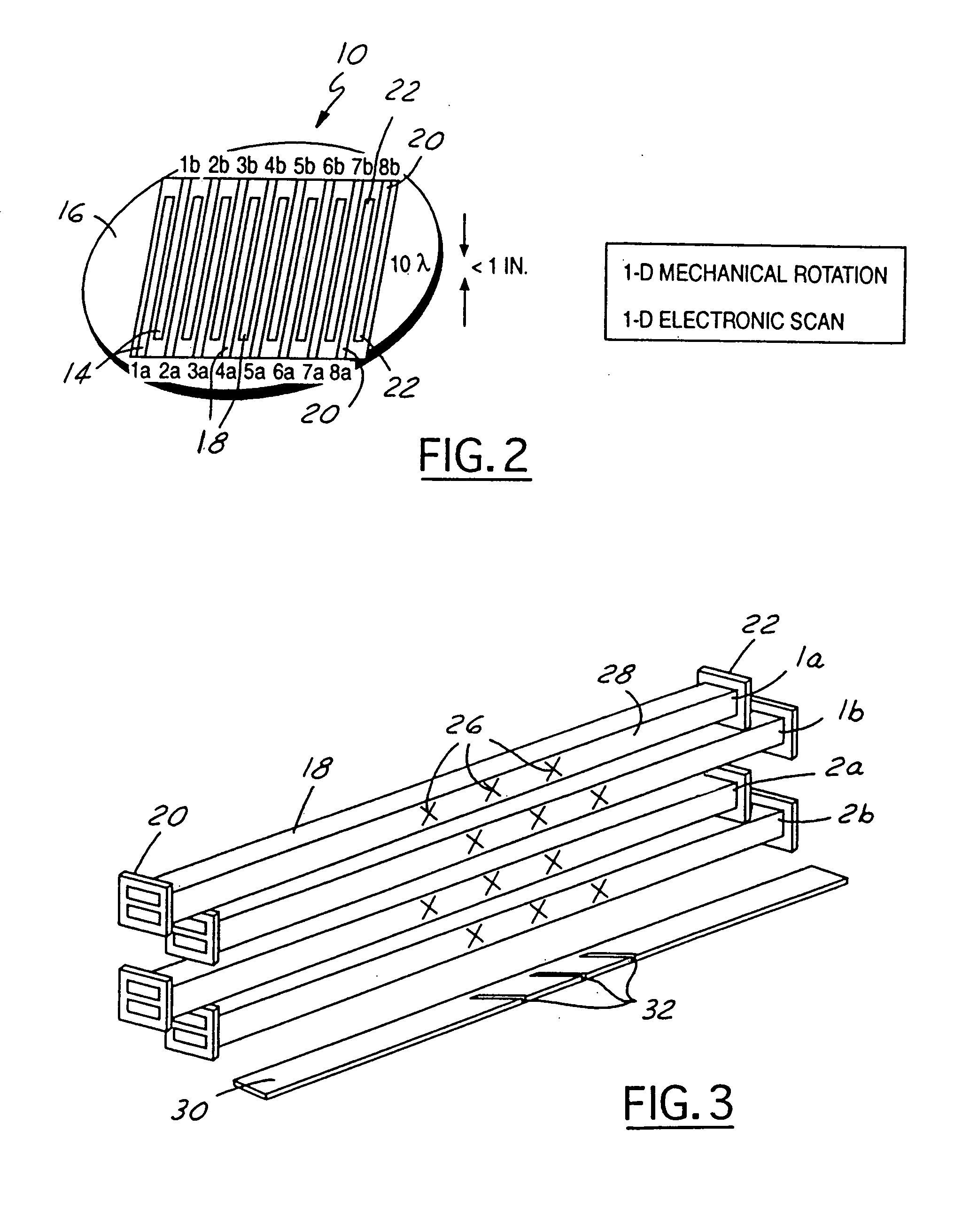
[0019]The preferred antenna 10 is illustrated in FIGS. 2 through 4 and provides a low cost and low profile configuration that also provides high performance. It should be understood that the illustrated antenna configuration is merely a preferred embodiment for achieving ...


PUM


Abstract

A low cost and low profile antenna for commercial use, either in a fixed or mobile condition is disclosed. The antenna has a generally flat circular plate that rotates to seam the azimuth direction. A plurality of radiation elements are positioned on the surface of the circular plate. The received signals are multiplexed, digitally converted, digitally beamformed, and then transferred to a digital receiver.

Description

TECHNICAL FIELD[0001]The present invention relates generally to a phased array antenna. More specifically, the present invention relates to a low cost, low profile tracking phased array antenna for use on a commercial satellite terminal for equatorial satellite constellation systems.BACKGROUND OF THE PRESENT INVENTION[0002]Current non-geostationary satellite technology directed towards the consumer market typically requires a tracking ground terminal. However, the tracking antennas with this current technology are expensive and bulky and, therefore, generally unacceptable to consumers. Current programs, including Ka-band and Ku-band programs require the development of a less costly, lower profile antenna.[0003]These current conventional multi-beam tracking ground terminals, include arrays with mechanisms for steering beams, such as phase shifters and / or gimbles. These arrays further include integrated mechanisms for simultaneously tracking the pointing directions of multiple beams, ...

Claims


Application Information

Patent Timeline
Patent Type & Authority Patents(United States)
IPC IPC(8): H01Q3/00H01Q1/32H01Q3/04H01Q3/26H01Q13/22H01Q21/00H04B7/185
CPCH01Q1/3275H01Q3/04H01Q3/26H01Q13/22H01Q21/005H04B7/18571
Inventor CHANG, DONALD C. D.MAYFIELD, WILLIAM W.NOVAK, III, JOHN I.TAORMINA, FRANK A.
Owner HUGHES ELECTRONICS
Learn More