Flexible wiring board and electrical device using the same

a flexible wiring board and electrical device technology, applied in the field of flexible wiring boards, can solve the problems of conventional flexible wiring boards, low yield of liquid crystal display devices, and easy wire breakage of copper foil patterns, and achieve the effect of preventing wire breakage and superior reliability

Inactive Publication Date: 2008-03-25
SHARP KK
View PDF28 Cites 48 Cited by
  • Summary
  • Abstract
  • Description
  • Claims
  • Application Information

AI Technical Summary

Benefits of technology

[0034]It is an object of the present invention to provide a flexible wiring board which includes an insulative protecting film for covering wiring and which is used in a bent form, which can surely prevent insulation failure of the insulative protecting film and easily prevent wire breakage when bent and has superior reliability, and to provide an electrical device using such a flexible wiring board.

Problems solved by technology

This was due to various drawbacks with the polymer film having a thickness thinner than 25 μm, such as difficulty in handling such a film due to its thickness, which causes wrinkles to generate and leads to misalignment, exposing the wiring which should not be exposed.
Despite this, the flexible wiring board thus prepared was very susceptible to wire breakage of the copper foil pattern 112 when the flexible wiring board was bent to mount it on the liquid crystal panel 120.
Accordingly, the yield of the liquid crystal display device was significantly low.
Thus, the conventional flexible wiring board has the problem of low wiring reliability.
However, in this structure, even though the copper foil pattern at the bending portion is plated to prevent rust, the copper foil pattern is not covered with the insulative protecting film over a wide range from a region in the vicinity of the connected portion to the region where bending is made, and thus the copper foil pattern is not protected both electrically and chemically over this area.
Thus, the copper foil pattern may not be shielded efficiently over the unprotected area, or wire breakage of the copper foil pattern may generate.
Further, since the flexible wiring board is bent at the plated portion, in the case where plating is made by Au / Ni plating, which offers superior connection stability, it becomes difficult to bend the copper foil pattern by the rigid Ni film and the copper foil pattern becomes susceptible to cracking.
Thus, wire breakage is more likely to occur when bent and reliability may suffer contrary to the intended purpose.
However, because this structure employs forming a wave on the insulative protecting film, manufacture of the flexible wiring board becomes complex, resulting in inefficient manufacture and increased manufacturing cost, and also the dimension of the flexible wiring board is increased for the height of the wave formed on the insulative protecting film.
However, since the ink cover lay is formed by applying liquid resin, it is susceptible to nonuniformity.
Thus, the foregoing arrangement has the problem of insulation failure especially at the side surface of the ribs of the conductor pattern.
Further, the liquid resin used to form the ink cover lay includes epoxy resin or polyimide resin (liquid polyimide), and the ink cover lay which is made of cured resist has poor insulation and poor reliability (certainty of offering insulative and physical protection is poor).
Also, since the curing temperature of polyimide is high, heating at high temperature is required.
Thus, with the flexible wiring board in which the copper foil pattern (wiring) is pasted by the copper foil adhesive, the copper foil adhesive, which generally has inferior heat resistance, deteriorates.
This sets a limit to the use of polyimide resin to an expensive adhesive-less flexible wiring board.
That is, the ink cover lay using polyimide resin has limited use compared with the insulative protecting film which is pasted by the adhesive.

Method used


Image

  • Flexible wiring board and electrical device using the same
  • Flexible wiring board and electrical device using the same
  • Flexible wiring board and electrical device using the same

Examples


first embodiment

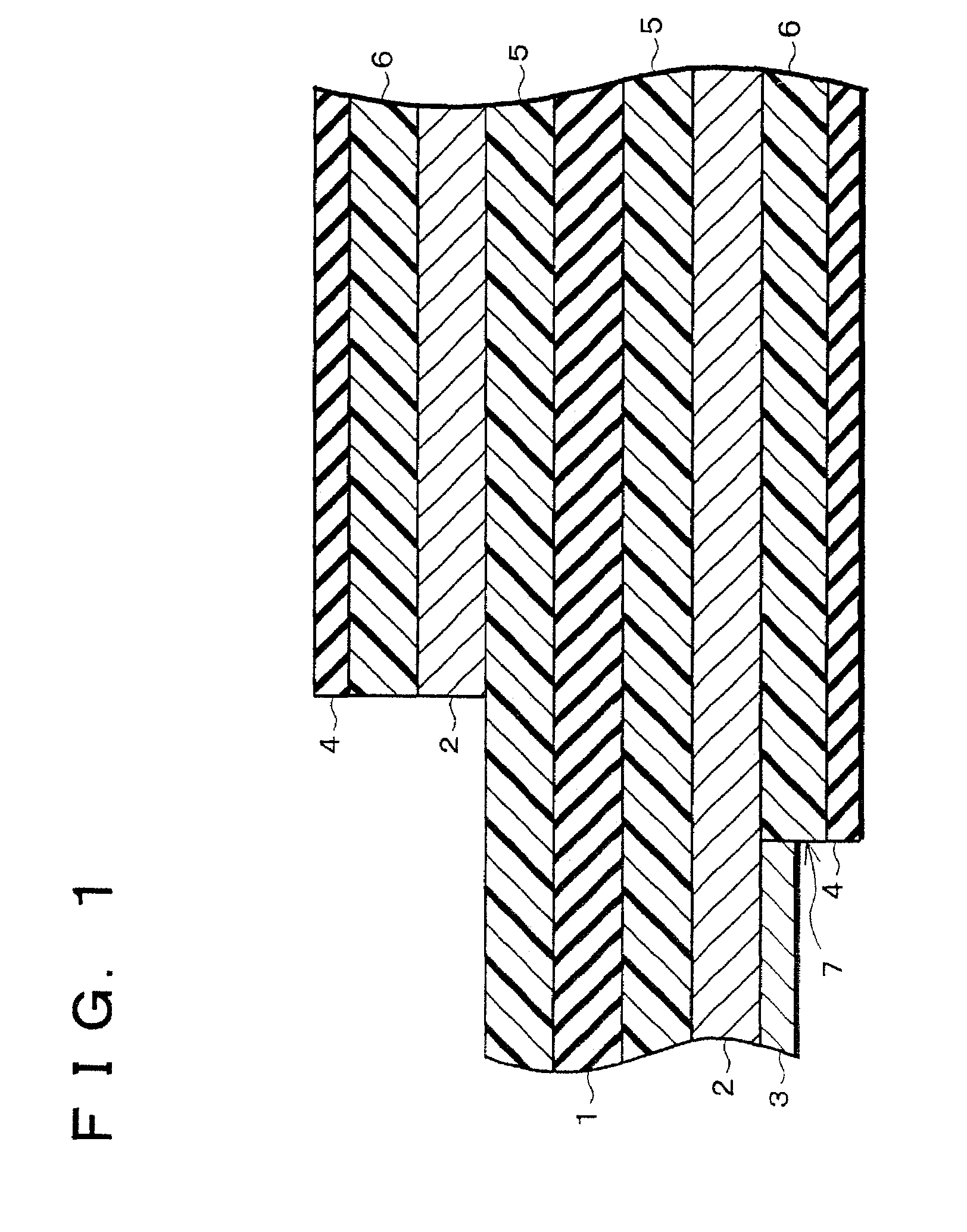
[0048]The following will describe one embodiment of a flexible wiring board in accordance with the present invention referring to FIG. 1 which shows a cross section of the flexible wiring board. As shown in FIG. 1, the flexible wiring board of the present embodiment includes a base polymer film made of polymer (flexible insulating substrate) 1, and copper foil patterns (wiring) 2 which are bonded on the both sides of the base polymer film 1 by copper foil adhesive layers 5, respectively.

[0049]The material of the base polymer film 1 is not particularly limited, but polyimide, which has superior flexibility and superior heat resistance, is preferable. The thickness of the base polymer film 1 is generally set within a range of 12.5 μm to 75 μm, for example, at 12.5 μm, 25 μm, 50 μm, or 75 μm. Base polymer film 1 thinner than 12.5 μm is difficult to handle and thus difficult to manufacture. The thickness of base polymer film 1 exceeding 50 μm is not preferable because the flexibility of...

second embodiment

[0076]The following will describe a Second Embodiment of the present invention referring to the drawings. Note that, for convenience of explanation, elements having the same functions as those described in the First Embodiment are given the same reference numerals and explanations thereof are omitted here.

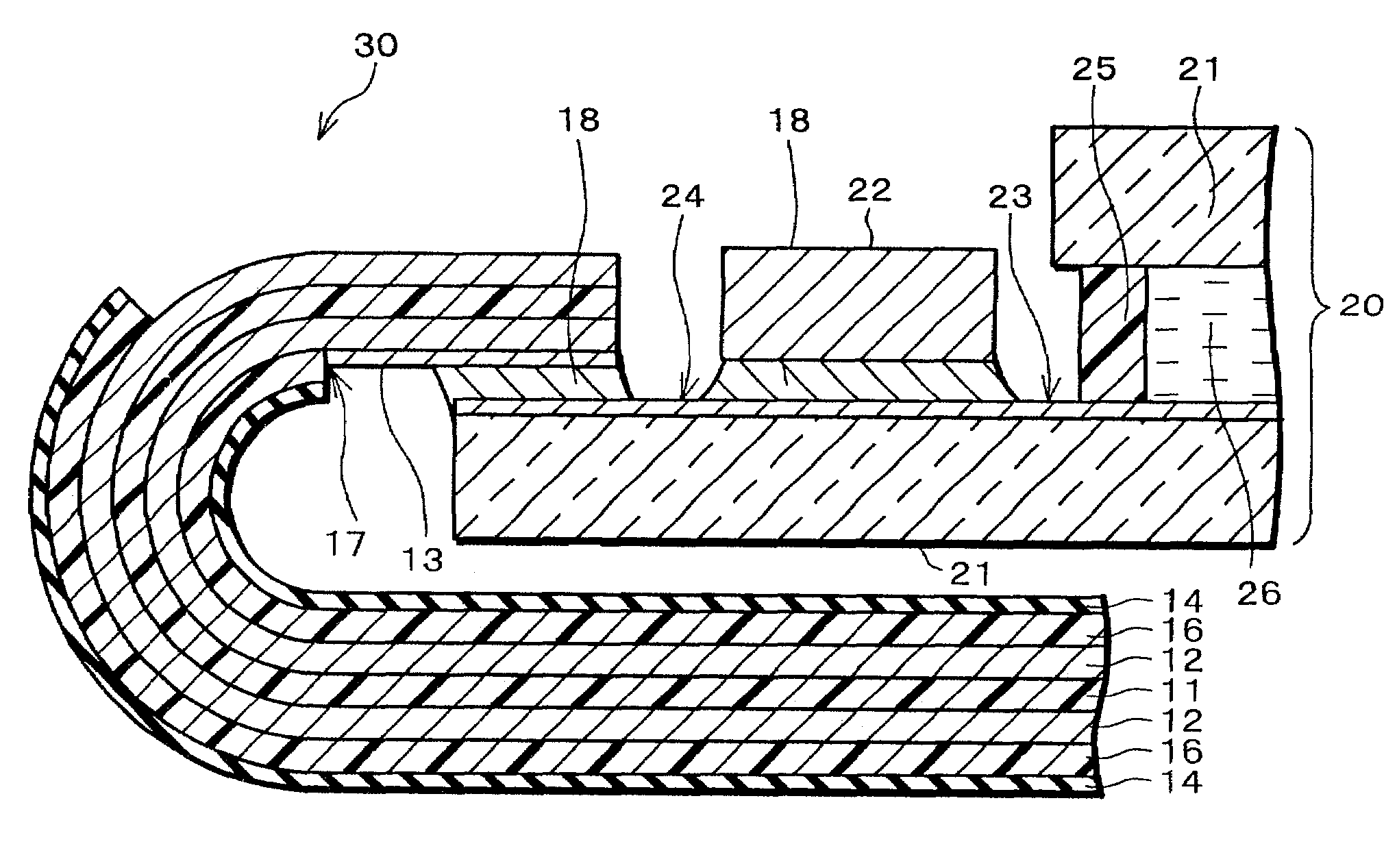
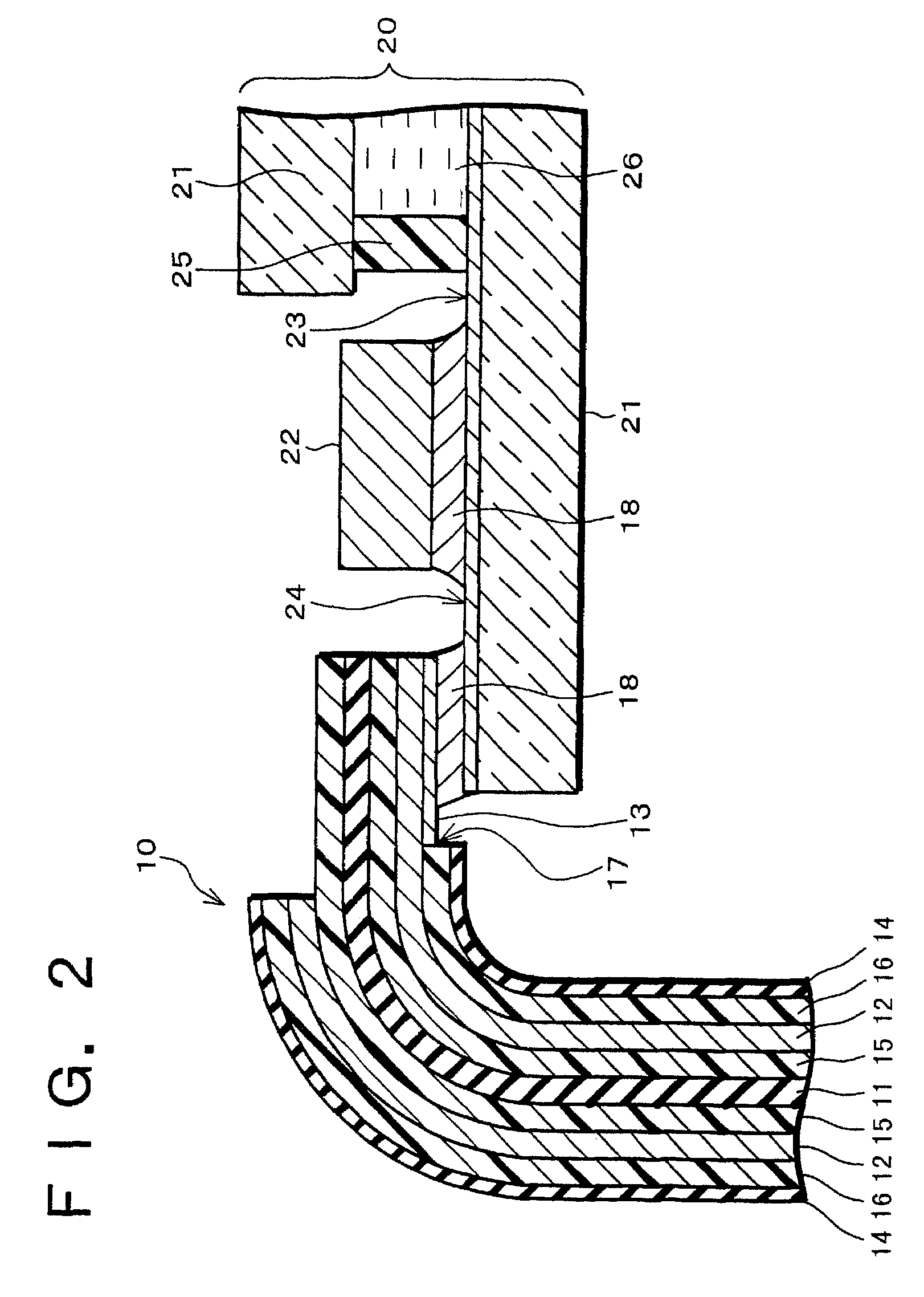
[0077]As shown in FIG. 3, a flexible wiring board 30 of the present embodiment is the same as the flexible wiring board 10 of the First Embodiment except that it is an adhesive-less flexible wiring board where the base polymer film 11 and the copper foil pattern 12 are directly bonded to each other without using the copper foil adhesive layer 15. In this case, the copper foil pattern 12 is formed, for example, by the method in which a copper foil is pressure-welded with the base polymer film and thereafter the copper foil is wet-etched.

[0078]As shown in FIG. 3, the flexible wiring board 30 is connected to an end portion on the upper surface of a larger glass substrate 21 (glass sub...

third embodiment

[0087]The foregoing embodiments described the flexible wiring boards having copper foil patterns on the both surfaces; however, a flexible wiring board having the copper foil pattern only on one surface can also be effected.

[0088]Thus, the following will describe another embodiment of the present embodiment referring to FIG. 4 employing a flexible wiring board having the copper foil pattern only on one surface. Note that, for convenience of explanation, elements having the same functions as those described in the First Embodiment will be given the same reference numerals and explanations thereof are omitted here.

[0089]As shown in FIG. 4, a flexible wiring board 40 of the present embodiment is the same as the flexible wiring board 10 of the First Embodiment except it does not include the copper foil adhesive layer 15, copper foil pattern 12, insulative protecting film adhesive layer 16, and insulative protecting film 14 on the outer side of the bend (upper side in FIG. 4) of the flex...


PUM

PropertyMeasurementUnit
thicknessaaaaaaaaaa
thicknessaaaaaaaaaa
thicknessaaaaaaaaaa

Abstract

A flexible wiring board is obtained as follows. A copper foil pattern is formed on the both surfaces of a base polymer film made of polyimide, etc. The copper foil pattern of the both sides, except for an end portion of the copper foil pattern of one surface, is covered entirely with an insulative protecting film made of polyimide, etc., for protecting the copper foil pattern, and the insulative protecting film and the copper foil pattern are bonded with each other by an insulative protecting film adhesive layer. On the exposed end portion of the copper foil pattern on one surface is formed a plated layer to be connected to an electrical component. The thickness of the insulative protecting film which is bonded with the surface on which the plated layer is formed is set to be thinner than the base polymer film. As a result, it is ensured that insulation failure of the insulative protecting film is prevented, and wire breakage of wiring when bent can easily be prevented.

Description

FIELD OF THE INVENTION[0001]The present invention relates to a flexible wiring board having wiring on a flexible insulating substrate, which is to be connected to various electrical components such as, in particular, liquid crystal display elements. The invention also relates to an electrical device which includes the flexible wiring board being connected to various electrical components, and, in particular, an electrical device (liquid crystal display device) including the flexible wiring board being connected to the liquid crystal display element.BACKGROUND OF THE INVENTION[0002]Conventionally used is a flexible wiring board having a wiring pattern on a flexible insulating substrate which is made of polymer such as polyimide for connection between various electrical components, in particular, between a liquid crystal display element and a driving circuit.[0003]An example of the conventional flexible wiring board will be described based on FIG. 5 which shows a cross section thereof...

Claims


Application Information

Patent Timeline
Patent Type & Authority Patents(United States)
IPC IPC(8): H05K1/00G02F1/1345G09F9/00H01L23/48H04Q1/14H05K1/02H05K1/14H05K1/18
CPCG02F1/13452H05K3/361H05K3/243H05K3/281H05K2201/0191H01L2924/0002H05K2201/0989H05K2201/10136H01L2924/00H04Q1/14
Inventor KAWAI, NORIKONAKASHIMA, TAKASHIYOSHIDA, HIROKAZU
Owner SHARP KK
Why Eureka
Try Eureka