

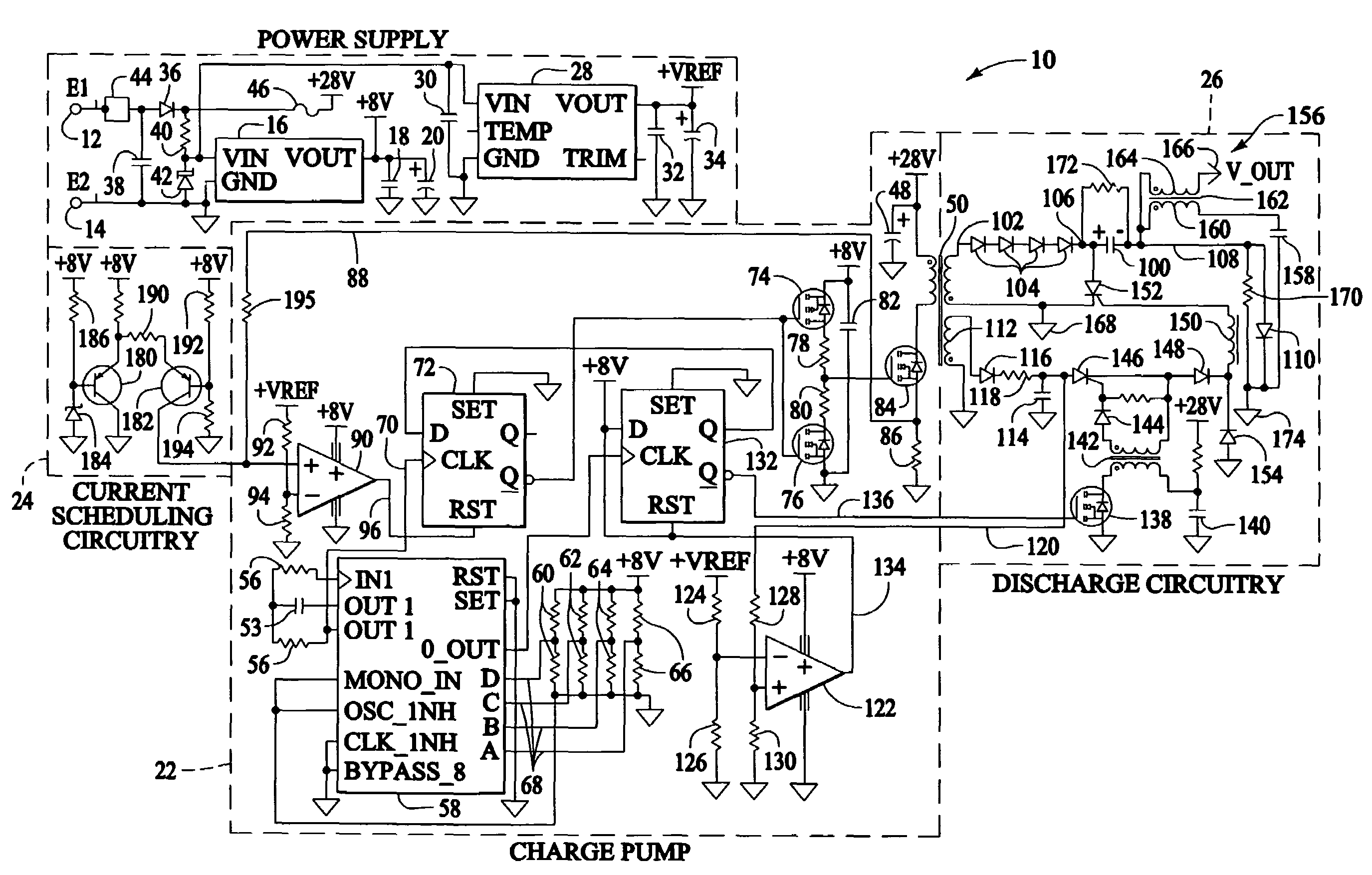
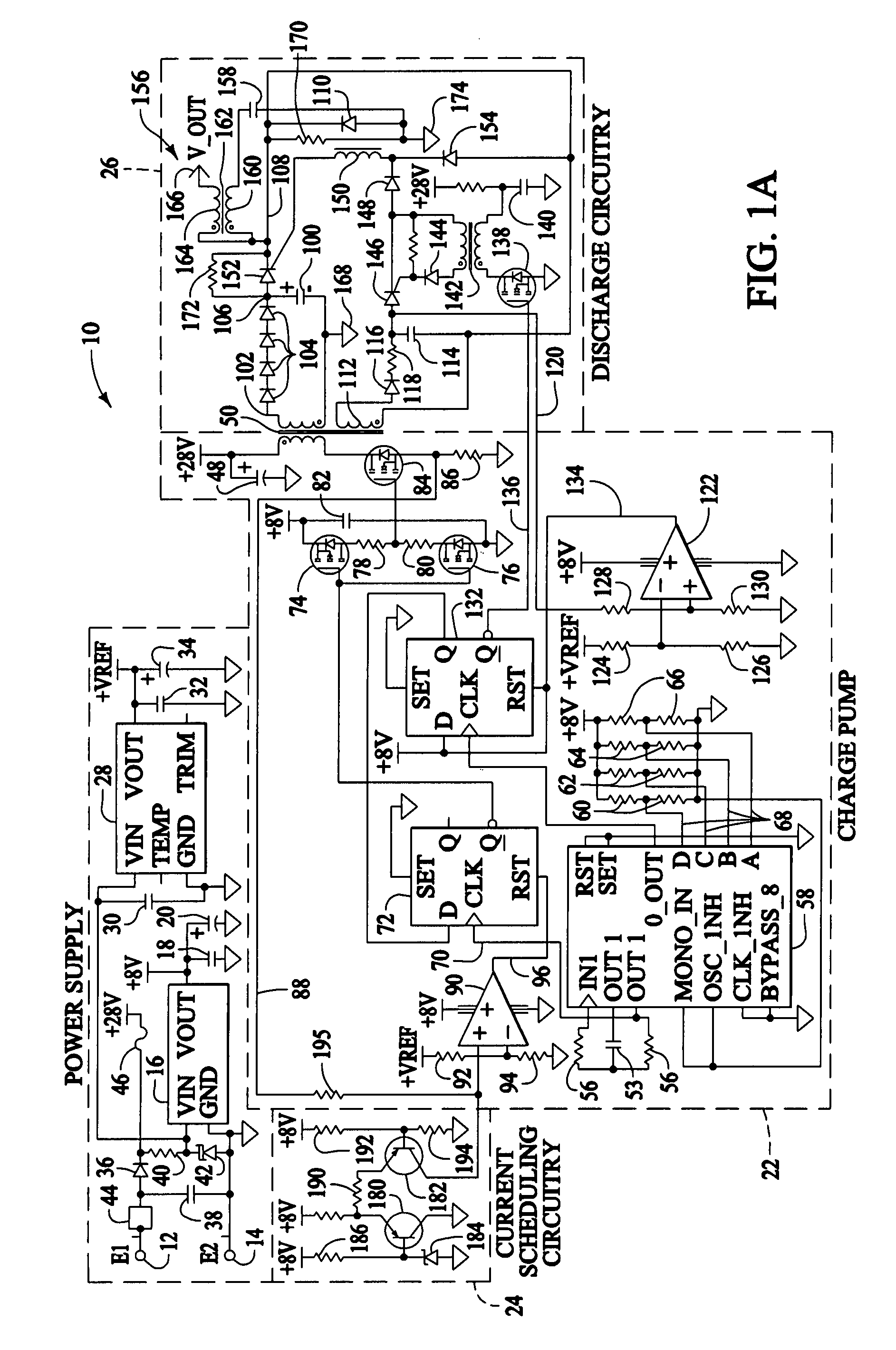
Solid state turbine engine ignition exciter having elevated temperature operational capability
a technology of solid-state turbine engines and operational capability, which is applied in the direction of machines/engines, lighting and heating apparatus, instruments, etc., can solve the problems of increased power dissipation, limited thermal performance of current-art solid-state ignition exciters, and limited leakage current related limitations of switching devices, so as to achieve high reliability operation
- Summary
- Abstract
- Description
- Claims
- Application Information
AI Technical Summary
Benefits of technology
Problems solved by technology
Method used
Image


Examples
Embodiment Construction
[0022]Operation of current prior art turbine engine ignition exciters at elevated ambient temperatures is limited by semiconductor leakage current. At elevated ambient temperatures, semiconductor leakage current increases exponentially with temperature which results in increased switching device power dissipation. This reduces product reliability, and if not carefully accounted for in the design process, can result in system failure due to thermal runaway effects. That is, at extreme temperatures device dissipation causes further device heating, which in turn causes further dissipation which progresses exponentially until the device is destroyed. This condition is exacerbated by the relatively high (approximately 3 kV) exciter tank circuit voltages commonly used in turbine engine ignition systems. The first preferred embodiment of the present invention employs a relatively low (i.e., approximately 1.5 kV to approximately 1.95 kV) tank voltage to further reduce dielectric and leakage...
PUM
 Abstract
Description
Claims
Application Information