Transmission apparatus, communication apparatus and mobile radio apparatus

a communication apparatus and transmission apparatus technology, applied in the field of transmission apparatus, can solve the problems of increasing the size of the transmission apparatus, increasing heat generation, and short usage time, and achieve the effect of reliable correction and control of delay

Inactive Publication Date: 2008-04-15
PANASONIC CORP
View PDF5 Cites 12 Cited by
  • Summary
  • Abstract
  • Description
  • Claims
  • Application Information

AI Technical Summary

Benefits of technology

[0020]It is therefore an object of the present invention to provide transmission apparatus capable of appropriately adjusting a delay time difference between an amplitude component and a phase component so as to reduce distortion of a vector modulation wave that is a transmission output to a sufficiently small level.
[0022]According to this configuration, by synchronously demodulating the modulation wave without dividing and extracting an amplitude component and phase component from the modulation wave, it is possible to detect distortion of the modulation wave occurring due to delay time differences between the amplitude component and the phase component, and carry out correction control on the delay time difference of the amplitude component modulation signal and the phase component modulation signal based on the detection results, so that it is possible to reduce distortion of the modulation wave down to a sufficiently small level.
[0024]According to this configuration, a signal is generated by the polar coordinate component modulation signal generating section in such a manner that a distortion component appears at a frequency component that is the second frequency f2 expressed by a value that is n (where n is an odd number of three or more) times the first frequency f1 in the event that a difference in delay time occurs in the paths the amplitude component modulation signal and phase component take to reach the amplifying section. The second frequency f2 is then extracted by the band filtering section. The controlling section also then controls the delay time adjusting section in such a manner that the level of the output signal of the band filtering section becomes small. It is therefore possible to reliably correct and control the delay time difference between the amplitude component modulation signal and the phase component modulation signal in the event of differences in delay time between the paths the amplitude component modulation signal and the phase component take to reach the amplifying section.
[0027]According to this configuration, a signal is generated by the polar coordinate component modulation signal generating section in such a manner that a distortion component appears at a frequency component that is a third frequency f3 expressed by the sum of a value that is n times the first frequency f1 and a value that is (n+1) times the second frequency f2 in the event that a difference in delay time occurs in the paths the amplitude component modulation signal and phase component take to reach the amplifying section. The third frequency f3 is then extracted by the band filtering section. The controlling section also then controls the delay time adjusting section in such a manner that the level of the output signal of the band filtering section becomes small. It is therefore possible to reliably correct and control the delay time difference between the amplitude component modulation signal and the phase component modulation signal in the event of differences in time delay between the paths the amplitude component modulation signal and the phase component take to reach the amplifying section.

Problems solved by technology

However, there is the drawback that the power efficiency of linear amplifiers is inferior compared to non-linear amplifiers such as C class to E class amplifiers.
Because of this, in the event that a conventional linear amplifier is used as a mobile type wireless apparatus such as a mobile telephone or mobile information terminal using a battery as a power source, because a class A or class AB linear amplifier of large power consumption is used, there is the drawback that usage time is short.
Further, in the event that a conventional linear amplifier is used as base station apparatus for a mobile communication system installed with a plurality of large power transmission apparatus, there is the drawback of inviting increase in size of the transmission apparatus and increased heat generation.
For example, the signal transmitting the amplitude component is amplitude component modulation signal a(t) and the signal transmitting the phase component is phase component modulation signal φ(t) or phase modulation wave Sc(t), and there is a problem that delay times occur in the paths these signals are transmitted on.
In a frequency division multiplex communication system where a plurality of channels are arranged on a frequency axis, this kind of broadening of the frequency spectrum causes interference with neighboring channels and therefore is not desirable.
As a result, the drawback occurs that it is not possible to measure the delay time between the amplitude component and the phase component in a precise manner.
Because of this, differences occur in measurement processing time due to differences in the circuit configuration of both circuits and it is therefore not possible to measure delay time in a precise manner.
It is therefore not possible to accurately measure differences in delay time between the amplitude component and the phase component.

Method used


Image

  • Transmission apparatus, communication apparatus and mobile radio apparatus
  • Transmission apparatus, communication apparatus and mobile radio apparatus
  • Transmission apparatus, communication apparatus and mobile radio apparatus

Examples


first embodiment

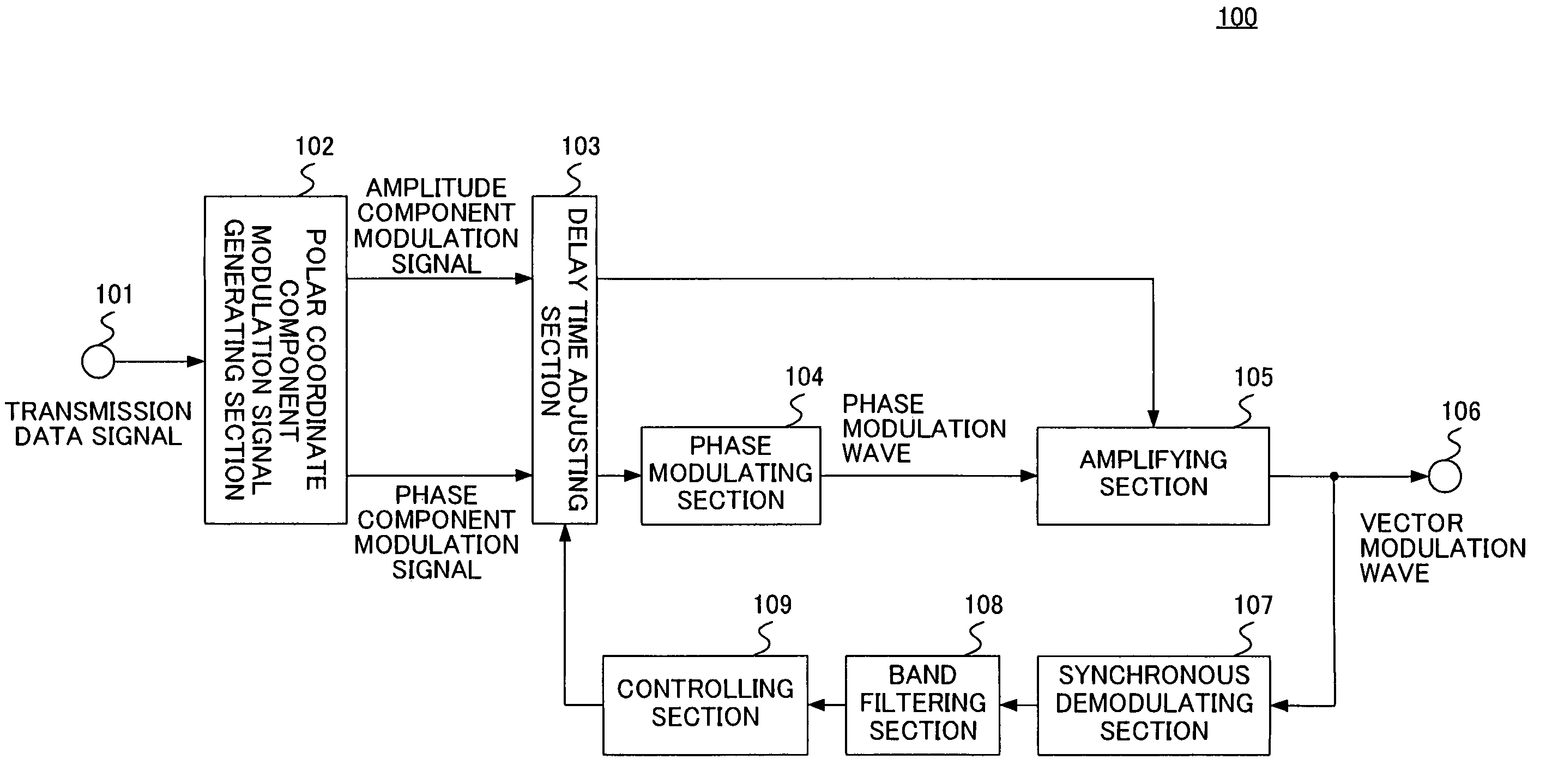
[0047]FIG. 4 is a block diagram showing a configuration for a transmission apparatus of a first embodiment of the present invention. Transmission apparatus 100 shown in FIG. 4 is comprised of transmission data signal input terminal 101 inputting a transmission data signal, polar coordinate component modulation signal generating section 102 forming an amplitude component modulation signal and a phase component modulation signal based on an inputted transmission data signal, delay time adjusting section 103 changing the delay time of an amplitude component modulation signal and a phase component modulation signal, phase modulating section 104 forming a phase modulation wave where a carrier wave is phase-modulated by the phase component modulation signal, amplifying section 105 receiving as input the phase modulation wave at a signal input terminal of transmission apparatus 100, with the amplitude component modulation signal applied to a power supply voltage terminal of transmission ap...

second embodiment

[0057]FIG. 6 is a block diagram showing a configuration for transmission apparatus of this embodiment. In FIG. 6, components that are the same as in FIG. 4 described in the first embodiment are given the same numerals and description thereof is omitted. Polar coordinate component modulation signal generating section 310 of transmission apparatus 300 of this embodiment is comprised of in-phase / quadrature component modulation signal generating section 311 and polar coordinate converting section 302. Further, in-phase / quadrature component modulation signal generating section 311 has sine-wave generating section 301 and phase shifting section 303.

[0058]In the case of this embodiment, in-phase / quadrature component modulation signal generating section 311 forms a first sine wave signal, as an in-phase component modulation signal, having a first frequency f1 and a first phase angle p1, and a second sine wave signal, as a quadrature component modulation signal, having a frequency that is th...

third embodiment

[0072]FIG. 10 shows a configuration for transmission apparatus of the present embodiment. Transmission apparatus 400 of this embodiment is different from transmission apparatus 300 of the second embodiment shown in FIG. 6 in that rather than having sine-wave generating section 301 and phase shifting section 303, in-phase / quadrature component modulation signal generating section 411 has sine wave generating sections 401 and 402, phase shifting sections 403 and 404, and adding sections 405 and 406.

[0073]Sine wave generating section 401 generates a sine wave of frequency f1 and transmits this to phase shifting section 403 and adding section 405. Sine wave generating section 402 generates a sine wave of frequency f2 that is different from frequency f1 and transmits this to phase shifting section 404 and adding section 405.

[0074]Phase shifting section 403 shifts and outputs the phase of the inputted sine wave in such a manner that the difference in the phase angle of the inputted sine wa...


PUM


Abstract

Transmission apparatus capable of reducing distortion of the vector modulation wave that is the transmission output to a sufficiently small level is provided. An amplifying section (105) generates a vector modulation wave based on an amplitude component modulation signal and a phase modulation wave. A synchronous demodulating section (107) detects the vector modulation wave, generates a synchronous demodulation signal, and sends this to a band filtering section (108). The band filtering section (108) extracts a signal of the frequency component of the distortion from a synchronous demodulation signal outputted by the synchronous demodulating section (107). A controlling section (109) then refers to the distortion component signal extracted by the band filtering section (108), controls a delay time adjusting section (103) in such a manner that the signal level of the distortion component becomes small, adjusts a delay time difference between the amplitude component modulation signal and the phase component modulation signal, and reduces distortion of the modulation wave.

Description

BACKGROUND OF THE INVENTION[0001]1. Field of the Invention[0002]The present invention relates to transmission apparatus carrying out polar modulation so as to generate a vector modulation wave. More particularly, the present invention relates to transmission apparatus synthesizing an amplitude component modulation signal and phase modulation wave so as to generate a vector modulation wave, and communication apparatus and mobile wireless apparatus mounted with this transmission apparatus.[0003]2. Description of the Related Art[0004]Normally, a power amplifier provided at an output section of transmission apparatus in a wireless communication system requires both low distortion and high efficiency. Power amplifiers serving this kind of use are classified into amplifiers using transistors as a current source or using transistors as switches. Amplifiers using transistors as a current source may be class A amplifiers, class AB amplifiers, class B amplifiers and class C amplifiers. Furthe...

Claims


Application Information

Patent Timeline
Patent Type & Authority Patents(United States)
IPC IPC(8): H03F1/32H04B1/04
CPCH03F1/0205H03F1/32H03F1/3247H03F1/3282H03F2200/102H04B2001/045H03F1/02H03F3/24
Inventor OKA, TATSUTO
Owner PANASONIC CORP
Why Eureka
Try Eureka