Laser apparatus, laser irradiation method, and manufacturing method of semiconductor device

a laser irradiation method and laser irradiation technology, applied in laser beam welding apparatus, lasers, manufacturing tools, etc., can solve the problems of difficult accurate generation, difficult to suppress a laser medium pressure fluctuation, and the above method limit, so as to achieve stable energy, and reduce the effect of laser beam fluctuation

Active Publication Date: 2008-04-15
SEMICON ENERGY LAB CO LTD
View PDF27 Cites 4 Cited by
  • Summary
  • Abstract
  • Description
  • Claims
  • Application Information

AI Technical Summary

Benefits of technology

[0041]Controlling the voltage to be applied to an electric discharge tube of a laser oscillator as in the above structure makes it possible to control the laser beam energy density with precision. Therefore, laser beam fluctuation can be cancelled out more securely than by the conventional method which uses a transducer and obtained laser beam can have steadier energy. More specifically, periodic cycle of energy fluctuation than rather than oscillation cycle of a laser beam can be suppressed.
[0042]When the above laser apparatus is used in crystallizing a semiconductor film, the semiconductor film can have more uniform crystallinity. A semiconductor device manufacturing method of the present invention can be used to manufacture integrated circuits and semiconductor display devices. In particular, when the method is used for a semiconductor element such as a transistor in a pixel portion of a semiconductor display device, for example, a liquid crystal display device, a light emitting device which has in each pixel a light emitting element, typically, an organic light emitting element, a DMD (Digital Micromirror Device), PDP (Plasma Display Panel), or an FED (Field Emission Display), lateral streaks due to energy distribution of laser beam used to irradiate the pixel portion is prevented from being recognized visually.

Problems solved by technology

The above method has a limit, however, to suppress a pressure fluctuation of a laser medium because it is difficult to accurately generate a pressure fluctuation of an inverted phase in a wave transducer.
Accordingly, in such method as the above method that the pressure fluctuation of the laser medium is counteracted using a transducer, it is difficult that a level of stability in energy of the irradiated laser beam reaches a satisfactory level.
When an output of a laser beam is not stable, it is difficult to perform a process to an object evenly.

Method used


Image

  • Laser apparatus, laser irradiation method, and manufacturing method of semiconductor device
  • Laser apparatus, laser irradiation method, and manufacturing method of semiconductor device
  • Laser apparatus, laser irradiation method, and manufacturing method of semiconductor device

Examples


embodiment mode 1

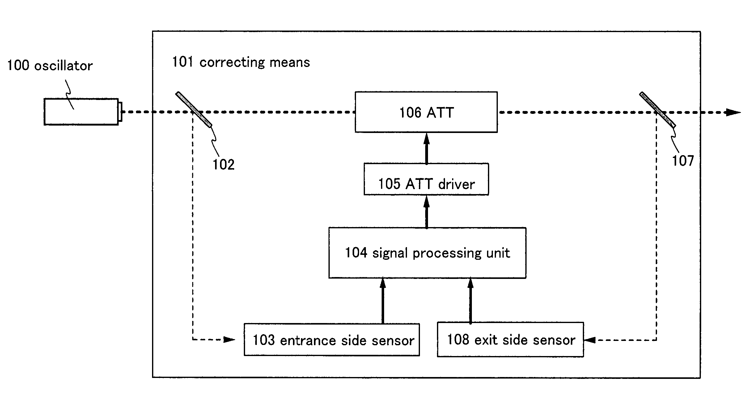
[0060]FIG. 1 is a block diagram of correcting means 101 of this embodiment mode. The correcting means 101 shown in FIG. 1 has an entrance side optical system 102, an entrance side sensor 103, a signal processing unit 104, an ATT driver 105, an ATT 106, an exit side optical system 107, and an exit side sensor 108.

[0061]The correcting means 101 shown in FIG. 1 samples laser beam on the entrance side of the ATT 106 and laser beam on the exit side of the ATT 106 both. Therefore, one optical system and one sensor are provided for sampling on each of the entrance side and the exit side. In FIG. 1, the entrance side optical system and the exit side optical system are discriminated from each other by denoting the former by reference symbol 102 and the latter by 107. The entrance side sensor and the exit side sensor are discriminated from each other by denoting the former by reference symbol 103 and the latter by 108.

[0062]The entrance side and the exit side are controlled by the same signal...

embodiment mode 2

[0088]FIG. 6 is a block diagram of correcting means 201 of this embodiment mode. The correcting means 201 shown in FIG. 6 has an optical system 202, a sensor 203, a signal processing unit 204, a voltage controlling means 205, and an electric discharge tube 206.

[0089]The correcting means 201 shown in FIG. 6 uses the optical system 202 to sample a part of laser beam emitted from the oscillator 200. The laser beam then enters the sensor 203, where the partial incident laser beam is converted into an electric signal. The electric signal is inputted to the signal processing unit 204. The sensor 203 can be any photoelectric conversion element as long as it is capable of generating an electric signal that contains laser beam energy fluctuation as data.

[0090]The signal processing unit 204 performs signal processing on the electric signal inputted. Out of energy fluctuation of the laser beam, periodic fluctuation is analyzed. For the signal processing, fast Fourier transformation and other v...

embodiment 1

[0100]Periodic fluctuation of laser beam energy varies depending on the oscillation frequency of an oscillator. This embodiment gives a description on the relation between the oscillation frequency of laser beam emitted from an excimer laser oscillator and the frequency of periodic fluctuation.

[0101]FIG. 7 shows the relation between the laser beam oscillation frequency (Hz) and the highest peak frequency (Hz) obtained by Fourier transformation. The horizontal axis indicates the oscillation frequency (Hz), and the vertical axis indicates the peak position (Hz) after Fourier transformation. Although measurements have been taken on different days, equal measurement conditions have been used except the oscillation frequency.

[0102]The peak frequency obtained by Fourier transformation means the frequency of periodic fluctuation of laser beam energy. The frequency of the periodic fluctuation repeatedly rises and drops in stages. Specifically, the frequency of the periodic fluctuation reach...


PUM

PropertyMeasurementUnit
frequencyaaaaaaaaaa
frequencyaaaaaaaaaa
oscillation frequencyaaaaaaaaaa

Abstract

It is an object to provide a laser apparatus, a laser irradiating method and a manufacturing method of a semiconductor device that make laser energy more stable. To attain the object, a part of laser beam emitted from an oscillator is sampled to generate an electric signal that contains as data energy fluctuation of a laser beam. The electric signal is subjected to signal processing to calculate the frequency, amplitude, and phase of the energy fluctuation of the laser beam. The transmittance of a light amount adjusting means is controlled in order that the transmittance changes in antiphase to the phase of the energy fluctuation of the laser beam and with an amplitude capable of reducing the amplitude of laser beam emitted from the oscillator, the control being made based on the phase difference between the phase of a signal that is in synchronization with oscillation of laser beam emitted from the oscillator and the phase calculated, on the energy ratio of the sampled laser beam to laser beam emitted from the oscillator, and on the frequency and amplitude calculated. In the light amount adjusting means, energy of the laser beam oscillated from the oscillator energy is adjusted.

Description

BACKGROUND OF THE INVENTION[0001]1. Field of the Invention[0002]The present invention relates to a laser apparatus and a laser irradiation method, specially a laser apparatus and a laser irradiation method that have a function to stabilize energy of an irradiated laser beam. The present invention also relates to a manufacturing method of a semiconductor device including a step for crystallizing a semiconductor film by the laser apparatus and the laser irradiation method.[0003]2. Description of the Related Arts[0004]Lasers are classified into a gas laser and a solid-state laser according to a laser medium and have various kinds. In the lasers, obtained wavelengths, energy values and pulse characteristics are different depending on the laser mediums. Applications of lasers have been searched according to characteristics of laser beams. Of the various lasers, YAG laser, CO2 laser, excimer laser and the like are mainly used for many industrial laser apparatuses.[0005]An excimer laser of...

Claims


Application Information

Patent Timeline
Patent Type & Authority Patents(United States)
IPC IPC(8): H01S3/13H01L21/268H01S3/00H01S3/131H01S3/134
CPCB23K26/422H01S3/131B23K26/702
Inventor MIYAIRI, HIDEKAZUSHIMOMURA, AKIHISATAKANO, TAMAEKOYAMA, MASAKITANAKA, KOICHIRO
Owner SEMICON ENERGY LAB CO LTD
Why Eureka
Try Eureka