Fast solution of integral equations representing wave propagation

a technology of integral equations and wave propagation, applied in computations using denominational number representations, instruments, design optimisation/simulation, etc., can solve the problems of increasing the functionalities of electronic products, reducing the size of electronic devices, and increasing data transmission rates, so as to reduce the number of unknowns, speed up computation, and high efficiency

Inactive Publication Date: 2008-04-15
CITY UNIVERSITY OF HONG KONG
View PDF14 Cites 7 Cited by
  • Summary
  • Abstract
  • Description
  • Claims
  • Application Information

AI Technical Summary

Benefits of technology

[0016]Preferably, the method includes calculating the rank table for the problem. The rank for a given set of parameters can be determined quickly by coarse-coarse sampling or partial wave analysis.
[0017]The further apart the two blocks are, the larger the size of the blocks we can use. In doing so, the matrix size of blocks can be increased while keep the rank still low. Because the UV is applied independently to each level and each block, the procedure facilitates parallel implementation.
[0021]As discussed below, the UV method improves computational efficiency and memory requirement, to O(N log N) per iteration step and memory requirement of O(N log N) as in the SMCG and the FMM techniques owing to the multilevel interacting blocks and loosely independent rank from block sizes.
[0023]Furthermore, as discussed below, methods which are embodiments of the invention typically have some of the advantages of both the SMCG and the FMM. They are Green's function independent, which means we can use them even for layered medium Green's function without major modifications. For example, using the layered medium Green's function, the impedance matrix can be derived. By using coarse sampling, the rank of the block impedance matrix can next be determined. The block matrix can then be written as the product of the UV matrix. This approach is applicable from quasistatics (a distinct class of very low frequency engineering problems in which the size of the region under consideration is smaller than one wavelength) to low frequency and to high frequencies. In addition, the UV method can be applied to both densely located elements as well as sparsely located elements very efficiently. Thus it is superior to the FMM and the SMCG-FFT methods for some cases.
[0024]In the particular case, mentioned above, of using an embodiment of the invention to solve a higher order partial waves impedance matrix, since the use of partial waves already reduces the number of unknowns of the problems, applying the UV method directly to the partial waves speeds up the computation even more, making the approach highly efficient for volume scattering problems.
[0036]In the latter case, the software product may be at least a part of an EDA software package which enables circuit design engineers to model not only individual integrated circuit components, but also complete electronic package structures and even the entire printed circuit board. The UV method can be used to reduce design risk and uncertainty and to provide necessary information to design engineers to make correct decisions. Because the method can be used for volume scattering problems with the use of partial waves as well, the methodology is also applicable to problems in materials and nanotechnology. It can be used to analyze photonic bandgap structures, the electronic scattering from nanostructures, the electronic bandstructures of nanomaterials and the electric and magnetic properties of composite materials.

Problems solved by technology

This leads to much higher data transmission rates, diminishing size of the electronic devices, and increase functionalities of the electronic products.
These make the design of the electronic devices more difficult and increase the challenges in the analysis of power and signal integrity problem.
However, conventional signal-integrity analysis tools are circuit-based and lack the accuracy required for high-speed integrated circuit design.
Thus, the computation becomes resource intensive when N is large.
This is impossible for a single PC processor today.
Thus matrix inversion cannot be used for such problems of large dense matrix.
Thus the bottleneck of the method is the calculation of the product of the impedance matrix and a column vector in each iteration step .
For these reasons, for complicated simulation problems with many unknowns, present day electronic design automation (EDA) solvers may take days or even weeks to complete the solution of a single instance of Maxwell's equation.
The MLFMM method exhibits computational complexity of O(N log N) per iteration and so does memory requirements.
It is not efficient for the sparse distributed scattering objects.
It is difficult to use with a multi-layered medium Green's function.
Its reliance on interpolation and anterpolation also makes it difficult to parallelize efficiently.
Also the method is inefficient at low and intermediate frequencies which are common for RF circuit problems because of the large number of multipoles still required for such problems.

Method used


Image

  • Fast solution of integral equations representing wave propagation
  • Fast solution of integral equations representing wave propagation
  • Fast solution of integral equations representing wave propagation

Examples


Embodiment Construction

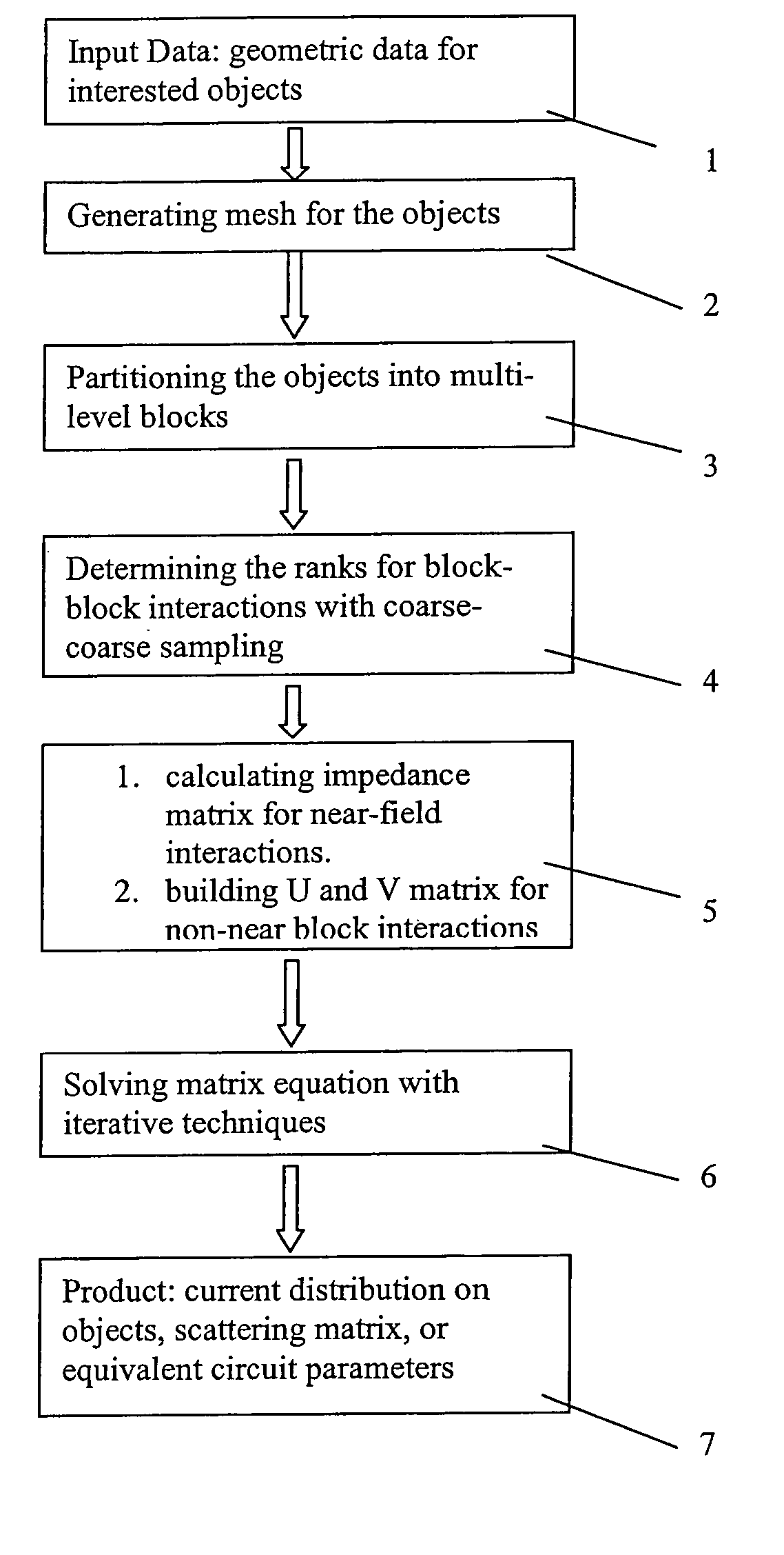
[0052]FIG. 13 shows the steps of a method which is an embodiment of the invention. In a first step (step 1) the method loads input data, describing the situation to be analyzed. In a second step (step 2) the method generates a basis in which the analysis will be performed (which may be a grid covering the region being analyzed, or a set of basis functions as described below). In a third step (step 3) the basis is partitioned into blocks at multiple levels. The impedance matrix is also partitioned into multi-level blocks. In a fourth step (step 4) the rank of the block-block impedance matrix is calculated with coarse-coarse sampling (defined below). In a fifth step (step 5) the impedance matrix for the near-field interactions is determined. For the non-near block impedance matrix, dense-rank and rank-dense sampling (defined below) is used to construct U and V matrices. In a sixth step (step 6) the matrix equation is solved iteratively. This allows the method to generate (step 7) the ...


PUM


Abstract

A technique for solving a set of wave equations in a region uses points arranged in a grid spanning the region or coefficients of wave expansion for objects located in the region. The grid points or the coefficients are partitioned into blocks on multiple levels, and block impedance matrices encoding the wave equations is derived for pairs of blocks. The block impedance matrix need not be calculated as it is written as the product of two non-square matrices, denoted U and V. Each of U and V have one linear dimension which is only of the order of the rank of the block impedance matrix levels. The rank is predetermined by coarse sampling. Two examples of the use of the invention are given: solving surface integral equations and Foldy Lax equations for partial waves.

Description

FIELD OF THE INVENTION[0001]The present invention relates to methods, apparatus and software products for solving integral equations representing wave propagation, and in particular scattering of waves. In some applications of the method the integral equations are solved in order to analyze a complex printed circuit board (PCB), Integrated Circuit (IC) packaging, high-performance interconnects, on-chip structures, patch antennas, or microstrip antennas. The methods can also be used to analyze photonic bandgap structures, meta-materials, the electronic scattering from nanostructures, the electronic bandstructures of nanomaterials and the effective electric and magnetic properties of composite materials.BACKGROUND OF THE INVENTION[0002]Integrated Circuits are the basic parts of most electronic systems such as computers, digital cameras, wireless communication systems, Internet devices, networking devices and systems, automotive electronic systems, control systems, and power electronic...

Claims


Application Information

Patent Timeline
Patent Type & Authority Patents(United States)
IPC IPC(8): G06F7/38
CPCG06F17/5018G06F17/5036G06F2217/40G06F2113/18G06F30/367G06F30/23
Inventor TSANG, LEUNGCHEN, DONGLI, QIN
Owner CITY UNIVERSITY OF HONG KONG
Why Eureka
Try Eureka