
Developing method and developing assembly

a technology of developing assembly and developing method, which is applied in the direction of developers, electrographic process devices, instruments, etc., can solve the problems of difficult to move from the developer, too large charge quantity of toner applied on the developer carrying member, and difficulty in charging toner

Active Publication Date: 2008-04-22
CANON KK
View PDF11 Cites 22 Cited by
  • Summary
  • Abstract
  • Description
  • Claims
  • Application Information

AI Technical Summary

Benefits of technology

The solution enables high-grade images without density decrease or non-uniformity, effectively preventing sleeve ghosts and fog, while maintaining low toner consumption even during extended continuous use, by ensuring uniform and quick triboelectric charging of toner particles.

Problems solved by technology

Where a toner tends to have high electric charges on toner particle surfaces, the toner applied on a developer carrying member may have too large charge quantity because of contact with the developer carrying member when the developer carrying member is repeatedly rotated.
Hence, the toner comes to stand immobile on the developer carrying member surface to become difficult to move from the developer carrying member to the latent image formed on the photosensitive drum.
The toner present on the developer carrying member surface in the immobile state makes it difficult for other toner to gain access to the developer carrying member, and as a result, the toner may come to be difficult to charge.
For this reason, the toner involved in development decreases, and hence problems are raised such as thin line images, decrease in image density of solid images, sleeve ghosts and density non-uniformity.
Such toner not properly charged because of the charge-up may become uncontrollable to flow out on the developer carrying member to cause what is called a blotch phenomenon in which blotchy or wavy non-uniformity comes about on images.
However, this developer carrying member may be insufficient in respect of the performance to provide toner with charges rapidly and uniformly and the ability to provide toner with charges appropriately, because the profile of surface unevenness of the resin coat layer formed on the developer carrying member surface is not sufficiently uniform.
In this case, with a decrease in diameter of the magnet roller, the magnetic flux density decreases necessarily, and this tends to cause fog greatly in a low-temperature and low-humidity environment.
Hence, the toner tends to be unstably charged.
This concurrently tends to cause faulty images such as sleeve ghosts, blotch phenomenon and density non-uniformity.
However, if the quaternary ammonium salt is added in a large quantity, the strength of the resin coat layer may be lowered to tend to cause variations of surface roughness.
However, for example, in an attempt to form line latent images of 200 μm in width and control the toner consumption, there has been such a problem that the line width obtained actually is considerably smaller than 200 μm, resulting in a lowering of the reproducibility of latent images.
However, such a toner tends to give a low solid-image density, and an attempt to make the image density higher results in an increase in toner consumption and also makes the lines thicker inevitably.

Method used


Image

  • Developing method and developing assembly
  • Developing method and developing assembly
  • Developing method and developing assembly

Examples


example 1

[0421]Using the developer carrying member produced as described above, evaluation was made in the following way.

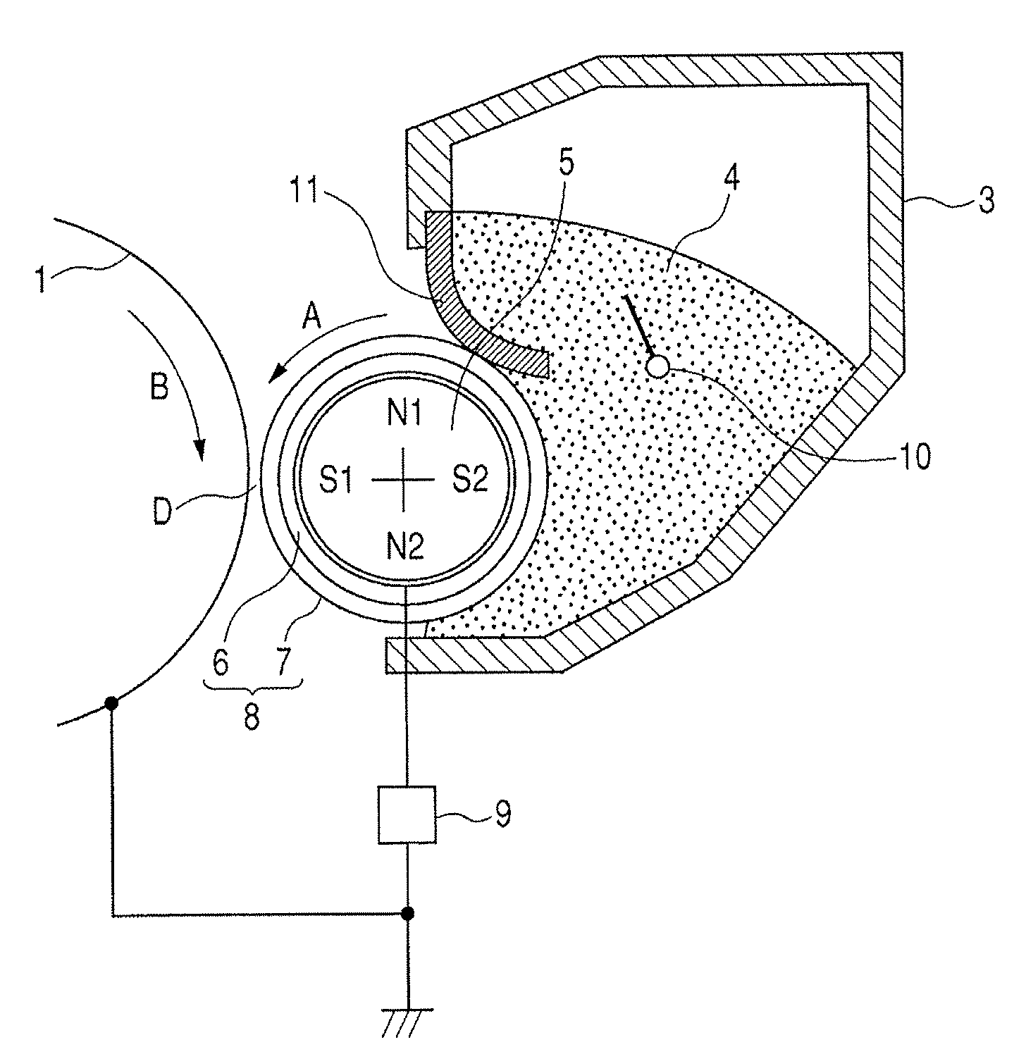
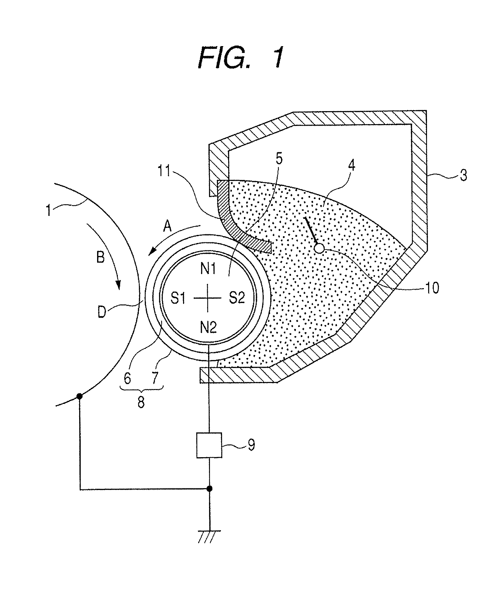
[0422]Developer Carrying Member S1 was set in a laser beam printer LASER JET 2300, manufactured by Hewlett-Packard Co., having the developing assembly shown in FIG. 1. As the toner, the above Magnetic toner 1 was used. As the developer layer thickness control member used in the developing assembly, a blade made of urethane as used in LASER JET 2300 was used, and its touch conditions were so changed as to be 40 g / cm (39.2 N / m) in linear pressure per 1 cm in the lengthwise direction of the developer carrying member.

[0423]As the development bias, the alternating electric field was set to be 1.6 kvpp and a frequency of 2,400 Hz, and the DC voltage (Vdc) was so set that development faithful to latent images were able to be faithfully developed (i.e., that line latent images of 200 μm and 4 dots were developed in a line width of 200 μm). In Example 1, the DC voltage was set to b...

examples 2 to 11

[0427]Using S2 to S10 and S14 as the developer carrying members and using T1 as the toner, evaluations were made in the same way as in Example 1. As a result, in all the cases, images on the level of no problem in practical use were obtained before and after the durability tests. These evaluation results are shown in Table 4.

examples 12 to 18

[0428]Using S1 as the developer carrying member and using T2 to T5 and T8 to T10 as the toners, evaluations were made in the same way as in Example 1. As a result, in all the cases, images on the level of no problem in practical use were obtained before and after the durability tests. These evaluation results are shown in Table 4.


PUM


Abstract

A developing method is provided in which a developer is carried on a developer carrying member, a thin layer of the developer is formed thereon and a latent image on a latent image bearing member is developed with a developer. The developer is composed of magnetic toner particles containing a binder resin and a magnetic powder. The magnetic powder has a saturation magnetization of 67.0 Am2 / kg to 75.0 Am2 / kg in a magnetic field of 79.6 kA / m (1,000 oersteds) and has a residual magnetization of 4.5 Am2 / kg or less. In the surface profile of the conductive resin coat layer of the developer carrying member, the relationship 1.00≦S / A≦1.65 is satisfied where S is a surface area of regions zoned by an area A of microscopic unevenness regions from which parts exceeding a reference plane by 0.5×r (r: weight average particle diameter (μm) of a toner used) or more have been excluded.

Description

[0001]This application is a continuation of International Application No. PCT / JP2006 / 313358, filed Jun. 28, 2006, which claims the benefit of Japanese Patent Application No. 2006-108856, filed Apr. 11, 2006.BACKGROUND OF THE INVENTION[0002]1. Field of the Invention[0003]The present invention relates to a developing method and a developing assembly.[0004]2. Description of the Related Art[0005]A number of methods are conventionally known as methods for electrophotography in which, in general, copies are obtained by forming an electrostatic latent image on a latent image bearing member by utilizing a photoconductive material and by various means, subsequently developing the electrostatic latent image with toner to form a toner image as a visible image, transferring the toner image to a recording medium such as paper as needed, and thereafter fixing the toner image onto the recording medium by the action of heat or pressure or the like.[0006]Image forming apparatus using the above elect...

Claims


Application Information

Patent Timeline
Patent Type & Authority Patents(United States)
IPC IPC(8): G03G15/08
CPCG03G9/0827G03G9/0833G03G9/0835G03G9/0838G03G15/09
Inventor OTAKE, SATOSHISHIMAMURA, MASAYOSHIAKASHI, YUSUTAKASAIKI, KAZUNORIDOJO, NENEITO, MINORUMAGOME, MICHIHISAYANASE, ERIKONAKAMURA, TATSUYA
Owner CANON KK
Learn More