Technique for applying direct resistance heating current to a specific location in a specimen under test while substantially reducing thermal gradients in the specimen gauge length

a technology of direct resistance heating and specimen gauge, which is applied in the direction of ohmic resistance heating, manufacturing tools, instruments, etc., can solve the problems of insufficient operator skill in that regard to properly utilize induction heating, insufficient specimen strength, and insufficient specimen strength, so as to prevent unwanted deformation, maintain specimen strength, and enhance control

Active Publication Date: 2008-04-29
DYNAMIC SYST INC
View PDF15 Cites 11 Cited by
  • Summary
  • Abstract
  • Description
  • Claims
  • Application Information

AI Technical Summary

Benefits of technology

[0020]For a given amount of heating current and as with any conductor, the self-resistive heating generated by the specimen and each of the collars is proportional to the resistance of each; the higher the resistance, the more heat that is generated. Because each collar encircles and abuts against the specimen adjacent to each end of the specimen gauge length but on a shoulder portion of the specimen that has a larger diameter and hence a lower resistance than the gauge length, additional heating is required along an interface region, i.e., the contact area, between the collar and the specimen surface to prevent heat loss at the collar that would otherwise yield an undesirable thermal gradient in the specimen gauge length. With the collar made of a material having a sufficiently high resistance relative to that of the specimen, then the collar as well as along the entire contact area, due to contact resistance all along that area, will collectively generate a sufficient amount of additional self-resistive heat to substantially eliminate this gradient or reduce it to a relatively low desired amount. When the temperature along the contact area exceeds that of the specimen itself—owing to the additional heat, then heat flows from the heated collar, through the gauge length, and into the specimen. Hence, heat flow outward from the contact area into the specimen will cancel heat flow coming back from the heated gauge length. Moreover, this additional heat will also compensate for any surface heat loss occurring in the ends and surface of the specimen and heat losses occurring through the insulation at the mechanical jaws, thus further eliminating or at least reducing any thermal gradients. Consequently, a rather uniform temperature distribution occurs across the entire gauge length as the specimen heats and a much lower temperature in the specimen end section located between each collar and a grip—when compared to temperatures that occur in specimen portions located outside the gauge length but resulting from use of conventional direct resistance heating methods.
[0022]Inasmuch as the grip attached to each end of the specimen is electrically insulated from the specimen along its attachment (gripping) area, no heating current passes in each specimen end section, i.e., in a region between that portion of the specimen lying between a collar and its proximate grip, hence producing no self-resistive heating in that portion. Consequently, that portion of the specimen has a much lower temperature than the gauge length thereby maintaining the strength of the specimen near its ends and causing any mechanical deformation, that would subsequently occur during a concurrent mechanical test program, to concentrate along the gauge length. This, advantageously and substantially prevents unwanted deformation from occurring during mechanical and thermal test programs in either of the specimen end sections.
[0023]Through the present invention, the mechanical and thermal systems in the overall testing system are separated from each other and can independently function of each other in order to provide enhanced control of each. As such and advantageously, the mechanical system can be designed to provide very stiff mechanical support and the thermal system can be designed to generate very small thermal gradients, if any at all, along the gauge length, thus substantially preventing unwanted mechanical deformation in the specimen end sections.
[0024]As a feature of the invention, the inventive technique can be readily applied to use with torsion specimens by simply modifying the specimen grips to impart relative rotation between the ends of the specimen rather than just applying tensile and / or compressive forces along a longitudinal axis of the specimen. The collars and their electrical connections need not be changed.

Problems solved by technology

While a properly designed furnace system produces a uniform temperature throughout the gauge length, the available heating rate produced by the furnace is substantially slower than those needed for simulating many manufacturing and fabrication processes.
While this scheme tends to adequately function, acceptable results generally occur only after significant effort has been expended on a trial-and-error basis to properly position the induction coils relative to the gauge length.
Thus, an operator often needs to have considerable skill in that regard to properly utilize induction heating.
Further, the induction coils tend to create localized hot spots within the specimen gauge length.
Consequently, a resulting temperature distribution along the gauge length will not be as uniform as would occur with a furnace.
While self-resistance heating is the most versatile, by virtue of its very high heating rates, and adaptable of the three heating techniques, it is typically the most difficult to control.
While a steep thermal gradient is useful for some types of tests such as weld heat-affected zone simulations, it is not desirable in certain other types of tests such as thermal mechanical fatigue tests.
While this approach creates a more uniform temperature distribution along the specimen length, it adversely affects various mechanical properties of both the grips and the specimen, particularly where the grips attach to the specimen which, in turn, prevents these grips from being used effectively for many types of tests.
By heating the specimen section between the gauge length and each grip to a similar temperature as the gauge length, that section is weakened which, in turn, allows unwanted deformation to occur in that section during a concurrent mechanical test program, thereby possibly distorting the results of that test program.
However, inasmuch as the heating current used in even these systems flows end-to-end through the specimen, specimen end sections adjacent to the gauge length may experience unwanted deformation during certain thermo-mechanical test programs.
Moreover, a majority of material testing systems currently in use, other than the GLEEBLE systems, and which have a servo-controlled hydraulic mechanical system, possess no inherent specimen heating capability.

Method used


Image

  • Technique for applying direct resistance heating current to a specific location in a specimen under test while substantially reducing thermal gradients in the specimen gauge length
  • Technique for applying direct resistance heating current to a specific location in a specimen under test while substantially reducing thermal gradients in the specimen gauge length
  • Technique for applying direct resistance heating current to a specific location in a specimen under test while substantially reducing thermal gradients in the specimen gauge length

Examples


Embodiment Construction

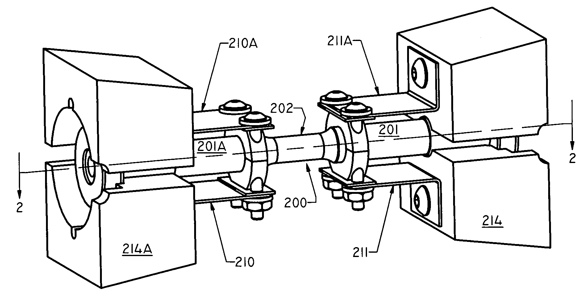
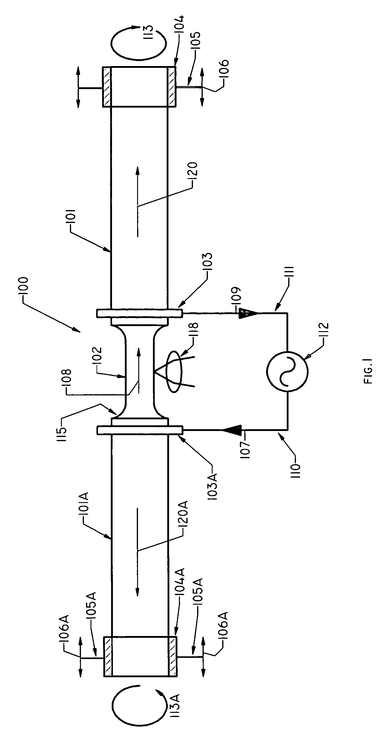
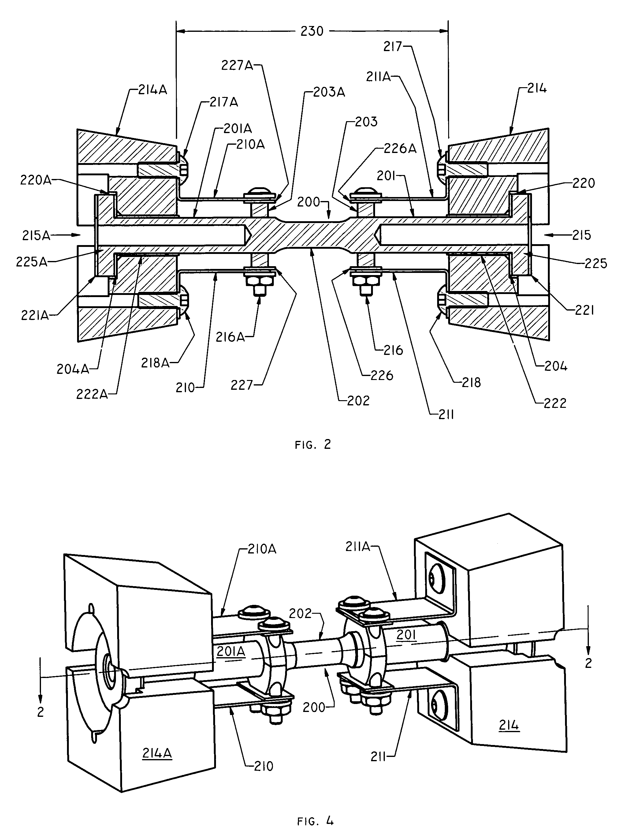
[0031]After considering the following detailed description, those skilled in the art will clearly realize that the broad teachings of the invention can be readily and advantageously utilized in conjunction with any one of a wide variety of material testing systems used for thermo-mechanical testing and physical simulation to impart a self-resistive specimen heating capability to those systems. Such testing systems would include not only tension and compression systems but also torsion systems. The self-resistive heating capability is well suited to replace induction and furnace heating systems commonly used to obtain essentially zero thermal gradients along a specimen gauge length. Moreover, even apart from its use with testing systems, the present invention can be used across a wide variety of industrial heating applications to produce localized self-resistive heating in conductive materials, such as, for example, to provide heat treatment to a metallic object either in a productio...


PUM

PropertyMeasurementUnit
lengthaaaaaaaaaa
lengthaaaaaaaaaa
lengthaaaaaaaaaa

Abstract

A technique for imparting direct resistance heating to a gauge length of a conductive metallic specimen under test and which can be used to add an independent dynamic thermal capability to a mechanical material test system. Specifically, a pair of, e.g., conductive collars, each of which encircles and abuts against a corresponding portion of the external surface of the specimen near an opposing end of its gauge length and inward of a corresponding grip. Each collar imparts additional self-resistive heat to the specimen along a circumferential collar / specimen interface. This additional heat appreciably reduces or cancels thermal gradients otherwise arising from self-resistive heating across the gauge length as well as compensates for thermal losses in each specimen end section. Through this arrangement, each specimen end section and the grips are not appreciably heated as the gauge length heats. The amount of additional heat is set by selecting a collar material to have a desired resistivity and also by appropriately dimensioning each collar.

Description

CLAIM TO PRIORITY[0001]This application claims priority of a now abandoned United States provisional patent application entitled “DIRECT RESISTANCE HEATING METHOD FOR APPLYING CURRENT TO A SPECIFIC LOCATION IN A MATERIAL”, assigned Ser. No. 60 / 652,491 and filed Feb. 11, 2005; and which is incorporated by reference herein.BACKGROUND OF THE INVENTION[0002]1. Field of the Invention[0003]The present invention relates to a technique, specifically apparatus and an accompanying method, for imparting direct resistance heating to a specific location in, for example, a conductive metallic specimen under test and which is particularly, though not exclusively, suited for use in adding an independent dynamic thermal capability to a mechanical test system. Advantageously, through use of the invention, axial thermal gradients that would otherwise appear along a gauge length of the specimen while it self-resistively heats can be set to a desired level or even substantially eliminated altogether, wh...

Claims


Application Information

Patent Timeline
Patent Type & Authority Patents(United States)
IPC IPC(8): G01N3/08
CPCG01N3/18H05B3/0014G01N2203/0222
Inventor LINDEMAN, NORMAN A.
Owner DYNAMIC SYST INC
Why Eureka
Try Eureka