
Laser trimming to tune the resonance frequency of a spiral resonator, the characteristics of a high temperature superconductor filter comprised of spiral resonators, or the resonance of a planar coil

a spiral resonator and resonance frequency technology, applied in the direction of superconductor devices, conductors, waveguides, etc., can solve the problems of increasing the difficulty in producing the desired hts filter pattern, affecting the stability of the filter, and affecting the quality of the filter, so as to prevent condensation and/or frost, prevent condensation accumulation, and ensure the effect of stabilization

Inactive Publication Date: 2008-05-06
EI DU PONT DE NEMOURS & CO
View PDF9 Cites 7 Cited by
  • Summary
  • Abstract
  • Description
  • Claims
  • Application Information

AI Technical Summary

Benefits of technology

This patent describes a method for tuning the resonance frequency of a high temperature superconductor spiral resonator, filter, or planar coil by ablating portions of the superconductor with a laser beam. The resonance frequency can be increased or decreased depending on the location of the trimming. The resulting resonance frequency shifts from multiple trimmings are additive. The invention also provides a process for forming a high temperature superconductor circuit element by ablating selected regions of a high temperature superconductor film while protecting other regions.

Problems solved by technology

It is both difficult and costly to try to control these parameters precisely during production.
The difficulty in producing the desired HTS filter pattern increases as the number of resonators or poles in the filter increases.
However, since the resonators generally vary in a random fashion, each pole of the filter must be individually tuned and the tuning of each pole affects every other pole in the filter.
The tuning process can typically take hours to perform.

Method used


Image

  • Laser trimming to tune the resonance frequency of a spiral resonator, the characteristics of a high temperature superconductor filter comprised of spiral resonators, or the resonance of a planar coil
  • Laser trimming to tune the resonance frequency of a spiral resonator, the characteristics of a high temperature superconductor filter comprised of spiral resonators, or the resonance of a planar coil
  • Laser trimming to tune the resonance frequency of a spiral resonator, the characteristics of a high temperature superconductor filter comprised of spiral resonators, or the resonance of a planar coil

Examples


example 1

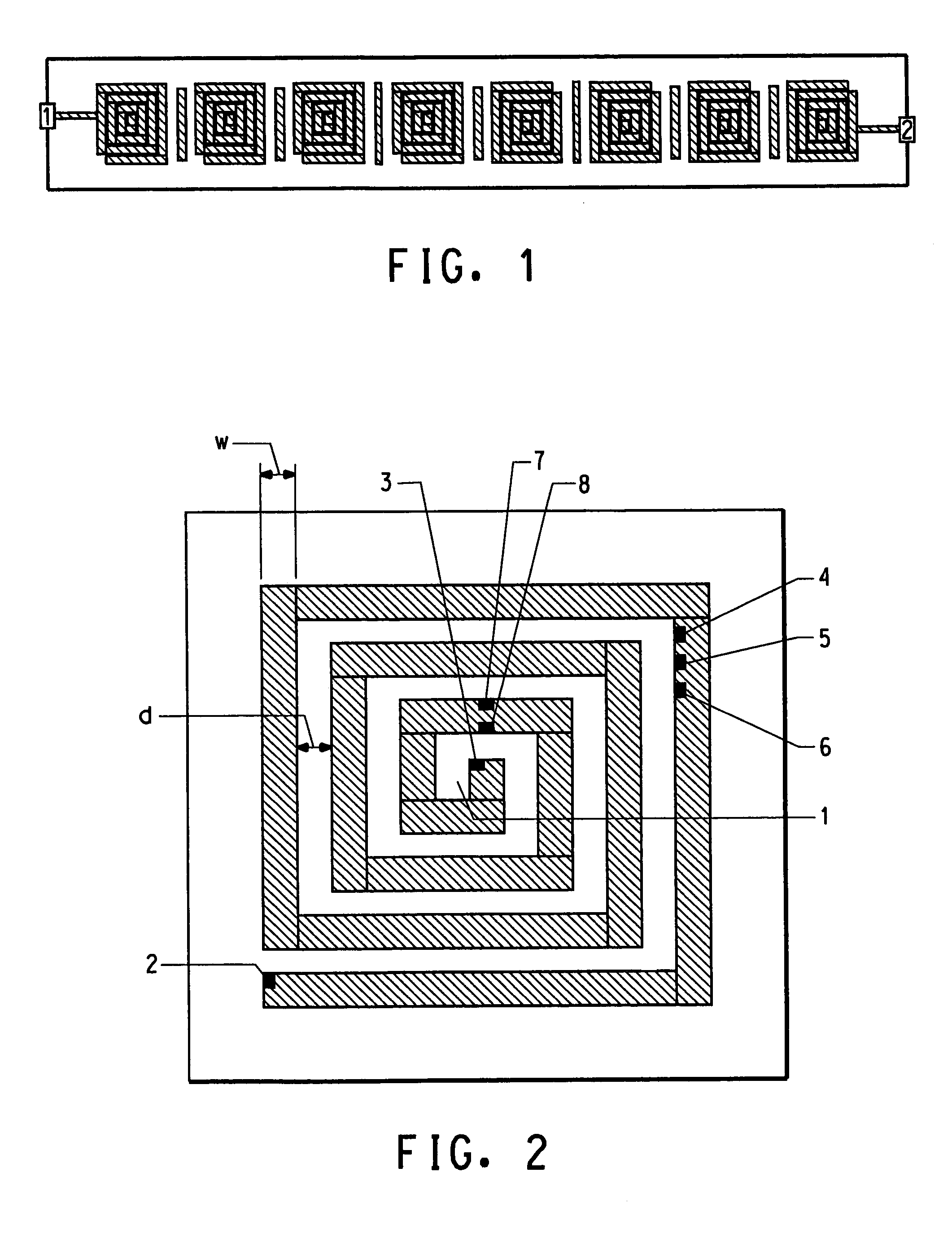
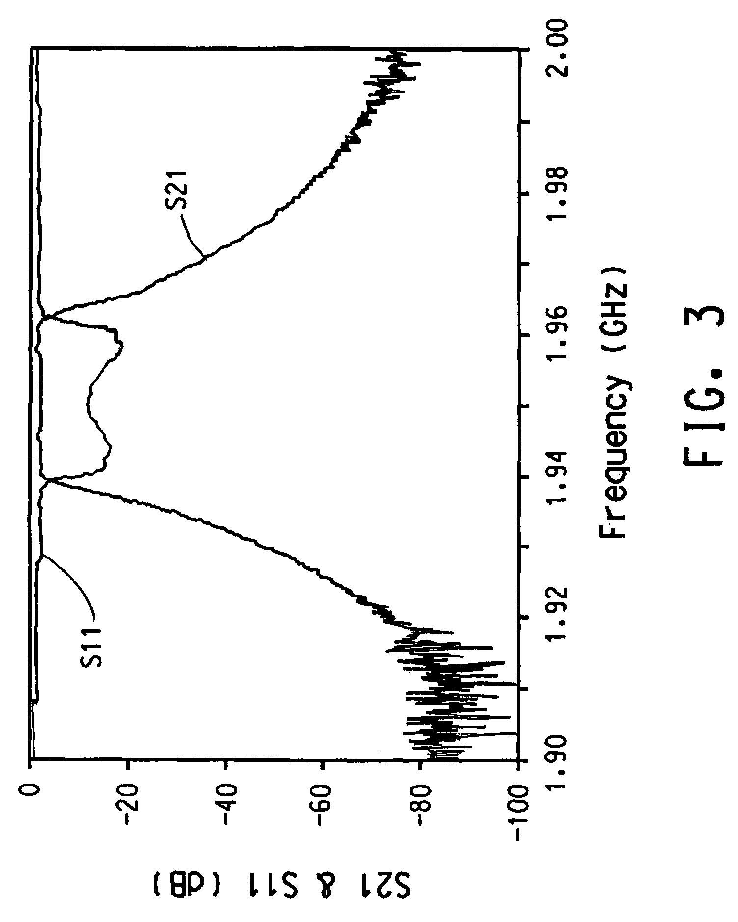
[0061]This example demonstrates the use of the laser trimming method of the invention to improve the characteristics of the band-pass region of an 8-pole filter with the design shown in FIG. 1, while holding the center frequency and the bandwidth of the band-pass region of the filter essentially constant.

[0062]The 8-pole HTS filter is produced using double-sided Tl2Ba2CaCu2O8 films on a LaAlO3 substrate and prepared as follows. A clean, polished single crystal LaAlO3 substrate, 75 mm×35 mm×0.5 mm, was obtained from MTI Corporation, Richmond, Calif. Off-axis magnetron sputtering of a Ba:Ca:Cu oxide target with a stoichiometry of 2:1:2 is used to deposit, at room temperature (about 20° C.), an amorphous precursor Ba:Ca:Cu oxide film onto both sides of the substrate. This amorphous Ba:Ca:Cu oxide film is about 550 nm thick and had a stoichiometry of about 2:1:2. The precursor film is then thallinated by annealing it in air for about 10 minutes at 850° C. in the presence of a powder mix...

examples 2-4

[0068]These examples are carried out using Sonnet EM software, obtained from Sonnet Software, Inc., Liverpool, N.Y. 13088, to simulate the performance of a HTS spiral resonator and demonstrate the changes in the resonance frequency of the HTS spiral resonator for various amounts of ablation at the outer end of the spiral. The following model is used. The substrate had a thickness of 0.508 mm and a dielectric constant of 24 and had a front side and a back side. The spiral resonator is in intimate contact with the front side of the substrate. A ground plane, which in practice would be a blank, i.e. continuous, HTS film, is on the back side of the substrate. The grounded top cover and side walls of the circuit are all sufficiently far from the spiral resonator so as to have negligible effect.

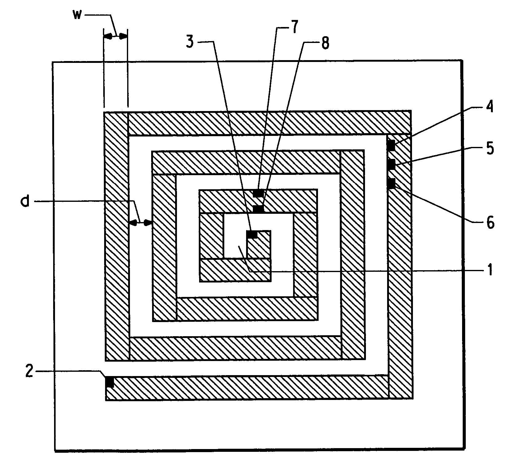
[0069]The rectangular spiral resonator shown in FIG. 5 is chosen for the simulation. The line widths of the spiral resonator are 308 μm with a gap of 44 μm between lines. The resonance frequency of...

examples 5-7

[0072]These examples are carried out using the same Sonnet EM software and the same rectangular spiral resonator and substrate used in Examples 2-4. As for the resonator of Examples 2-4, the resonance frequency of the spiral resonator with no material removed is 1.8607 GHz.

[0073]As shown in FIG. 7A, for Examples 5-7 material is removed at the inner end 9 of the resonator to simulate the removal of HTS material there by laser ablation. The location of removal is shown in detail in FIG. 7B where the amount of material removed is shown to be a cut of depth d and length 1. In each example, the depth of the material removed is the same, i.e. d=44 μm. The lengths 1 of the cuts are 44 μm for Example 5, 88 μm for Example 6 and 132 μm for Example 7. The resonance frequency is determined for the spiral resonator of each of the examples. The resonance frequencies are 1.8605 GHz for Example 5, 1.8603 GHz for Example 6 and 1.8600 GHz for Example 7. The resonance curves and frequencies are shown ...


PUM

PropertyMeasurementUnit
thickaaaaaaaaaa
thicknessaaaaaaaaaa
dielectric constantaaaaaaaaaa

Abstract

This invention provides a laser trimming method for tuning the frequency of a spiral resonator, and for improving the characteristics of a high temperature superconductor filter comprised of high temperature superconductor spiral resonators, by tuning the individual high temperature superconductor spiral resonators. This invention also provides a method for tuning the resonance frequency of a high temperature superconductor planar coil. This invention also provides a laser ablation process for creating high temperature superconductor circuit elements.

Description

[0001]This application claims the benefit of U.S. Provisional Application No. 60 / 523,988, filed on Nov. 21, 2003, which is incorporated in its entirety as a part hereof for all purposes.FIELD OF THE INVENTION[0002]This invention relates to laser trimming to tune the resonance frequency of a spiral resonator, to tune individual spiral resonators of a high temperature superconductor filter to improve the filter characteristics, or to tune the resonance frequency of a planar coil.BACKGROUND OF THE INVENTION[0003]High temperature superconductor (HTS) filters have applications in telecommunication, instrumentation and military equipment. The HTS filters have the advantages of extremely low in-band insertion loss, high out-of-band rejection and steep skirts due to the extremely low loss in the HTS materials. In a typical design, HTS filters and mini-multiplexers are comprised of spiral resonators.[0004]Filter performance is highly dependent on the frequencies of the resonators of which th...

Claims


Application Information

Patent Timeline
Patent Type & Authority Patents(United States)
IPC IPC(8): H01P1/203H01P3/08H01B1/00H01F17/00H01F21/02H01F41/04H01P7/00H01P11/00H10N60/01
CPCH01F41/045H01L39/2467H01P7/005H01P11/008H01F17/0006H01F21/02Y10S505/70H10N60/0688H01P7/08H01P1/208H01P9/02
Inventor ALVAREZ, ROBBY L.ESTRADA, CALIXTOGUO, JUINN-SHENGROSSI, ROBERT J.SHEN, ZHI-YUAN
Owner EI DU PONT DE NEMOURS & CO
Learn More