Eureka AIR delivers breakthrough ideas for toughest innovation challenges, trusted by R&D personnel around the world.

Power supply unit and computer

Active Publication Date: 2008-05-06
LENOVO PC INT
View PDF12 Cites 16 Cited by
  • Summary
  • Abstract
  • Description
  • Claims
  • Application Information

AI Technical Summary

Benefits of technology

[0016]Thus, because the first power supply unit according to the present invention comprises a plurality of power supply circuits having different power conversion efficiency characteristics for converting an input voltage to a predetermined voltage and allows power output to be provided from one of the plurality of power supply circuits which converts power most efficiently according to the state of a control signal, the first power supply unit can provide a high power conversion efficiency under a wide range of loads from light to heavy, and the output precision of each power supply circuit can be made substantially the same as that of the entire power supply unit because the plurality of power supply circuits does not operate concurrently. As a result the first power supply unit can achieve a higher precision with low costs.
[0034]Thus, with the computer according to the present invention, high efficiencies can be achieved under various load conditions from light to heavy and therefore power consumption can be reduced, because a plurality of power supply circuits is provided having different power conversion efficiency characteristics and output power is allowed to be provided from one of the plurality of power supply circuits which converts power most efficiently according to the state or amount of power consumption.

Problems solved by technology

Accordingly, higher precision components must be used, or the number of components must be increased, resulting in higher costs.
The system described in the above-mentioned Published Unexamined Patent Application No. 8-149804 also suffers a reduced lower output voltage precision due to a voltage drop over an output load current detection resistance on the output side.

Method used


Image

  • Power supply unit and computer
  • Power supply unit and computer
  • Power supply unit and computer

Examples


first embodiment

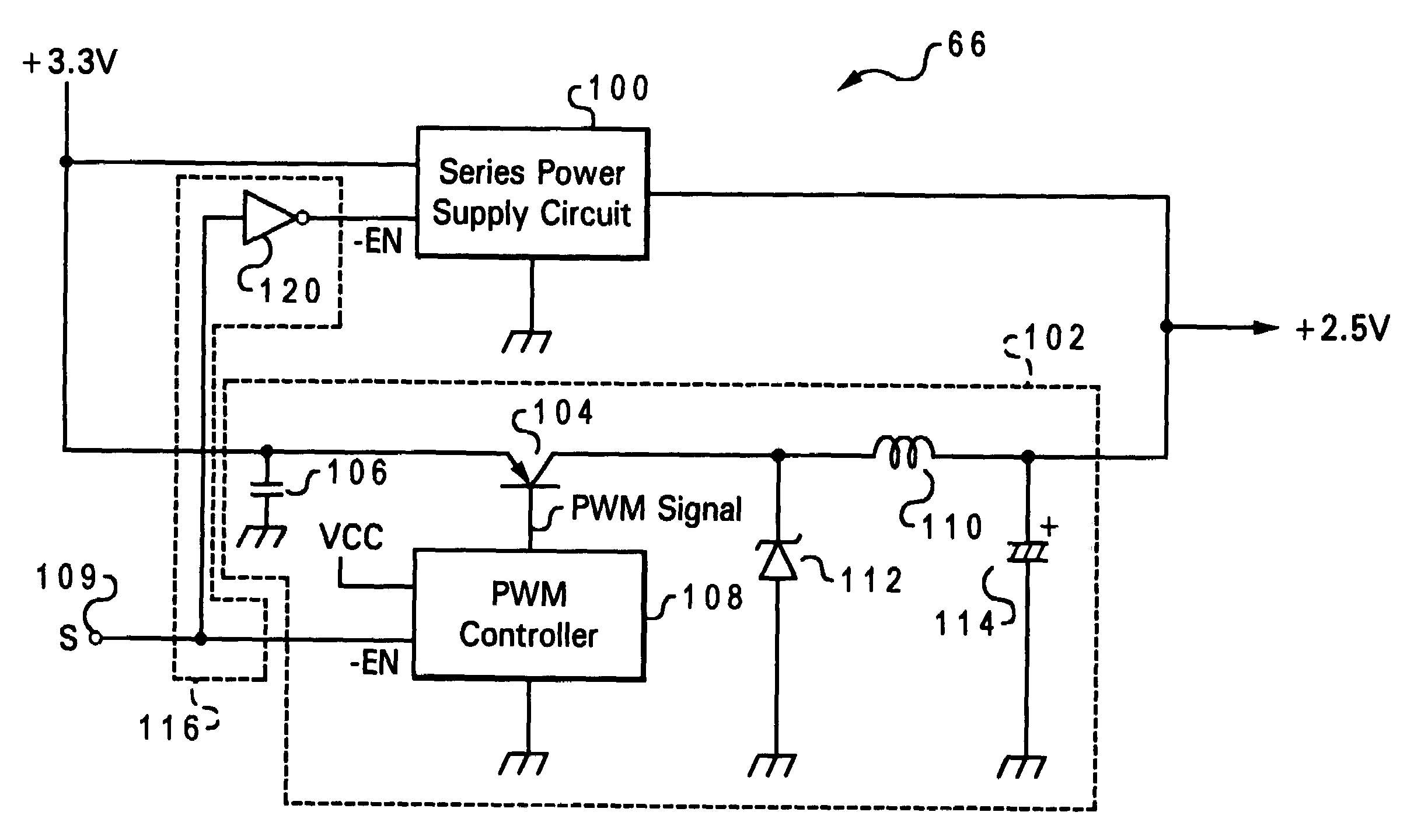
[0064]Referring to FIG. 3, there is depicted is a schematic representation of DC / DC converter 66 in accordance with the present invention. Within DC / DC converter 66 are a series power supply circuit 100 and a switching power supply circuit 102. Series power supply circuit 100 has power conversion efficiency characteristics for load conditions as shown in FIG. 8(B) while switching power supply circuit 102 has power conversion efficiency characteristics as shown in FIG. 8 (A). In accordance with the inventive principles as set forth herein, series power supply circuit 100 acts as a power supply circuit for lighter loads and is replaced by switching power supply circuit 102 for heavier loads.

[0065]Series power supply circuit 100 is connected to a power supply (not shown) which supplies a DC voltage of +3.3 V, and is also connected to a ground. An enable terminal (−EN) provides an activation control input signal to series power supply circuit 100. Series power supply circuit 100 is conf...

second embodiment

[0089]Referring now to FIG. 5, there is depicted a schematic diagram of a DC / DC converter 66′ in accordance with a the present invention. As shown in FIG. 5, DC / DC converter 66′ is similar to the DC / DC converter 66, except that no standby signal is used. Furthermore, a detecting circuit 140 comprising a current sense amplifier 122, a comparator 124, and resistances RS, R1, R2 and are incorporated within DC / DC converter 66′.

[0090]A resistance RS is utilized for detecting the amount of current through the source of each power supply circuit on a line for applying a DC voltage of +3.3 V to switching power supply circuit 102. Both terminals of the resistance RS are connected to the input terminals of current sense amplifier 122, which is configured as an IC. The output of current sense amplifier 122 is connected to the negative input (inverting input) of a comparator 124 and also to the non-grounded terminal of resistance R1.

[0091]A DC reference voltage Vref is applied to the positive i...


PUM


Abstract

A series power supply circuit and a switching power supply circuit are combined within a single power supply unit. The switching power supply circuit provides an efficiency lower than that of the series power supply circuit under a light load and provides an efficiency higher than that of the series power supply circuit under a heavy load. A standby signal that is asserted under a light load and is deasserted under a heavy load is input to a negative logic enable terminal (−EN) of the series power supply circuit through an inverter0. The standbysignal is directly input to the negative logic enable terminal (−EN) of a PWM controller in the switching power supply circuit.

Description

BACKGROUND OF THE INVENTION[0001]1. Technical Field[0002]The present invention relates to a computer power supply unit, and in particular to a power supply unit which operates efficiently under a wide range of load conditions from light to heavy within a computer.[0003]2. Description of the Related Art[0004]In a personal computer (PC) a DC (direct current) / DC converter is typically provided for converting an applied DC voltage into various DC voltage levels, such as 2.5 V or 3.3 V, that are supplied to different parts (load) of the PC. Among the types of power supply circuits that can be used as such DC / DC converters are switching power supply circuits and series power supply circuits.[0005]FIG. 8(A) illustrates an example power conversion efficiency measurement for a switching power supply circuit (commercially available as an integrated circuit (IC) chip) wherein the input voltage is 3.3 V and the output voltage is 2.5 V. As depicted in FIG. 8(A), the switching power supply circui...

Claims


Application Information

Patent Timeline
IPC IPC(8): G06F1/26H02M3/155H02J1/10
CPCG06F1/263H02J1/102H02M2001/0032H02M2001/0045Y02B70/16H02J1/001H02M1/0032H02M1/0045Y02B70/10
Inventor ODAOHHARA, SHIGEFUMI
Owner LENOVO PC INT
Why Eureka
Eureka Blog
Learn More