Composite metal article and method of making

a metal article and composite technology, applied in the field of composite metal articles, can solve the problems of affecting the heat-affected area adjacent to the alloy of the two metals, and reducing the service life of the metal article, so as to achieve superior cutting and wear resistance, the effect of superior bonding

Inactive Publication Date: 2008-05-20
WILLIAM ENG LLC
View PDF72 Cites 23 Cited by
  • Summary
  • Abstract
  • Description
  • Claims
  • Application Information

AI Technical Summary

Benefits of technology

[0014]The present invention provides a composite metal article that exhibits superior bonding between the dissimilar metals. The composite article is capable of being further processed into saw blades or other useful articles. A saw blade with superior cutting and wear-resistant properties is provided.
[0015]The present invention also provides a simple and effective method for forming a composite metal article. According to one aspect of the invention, a method of making a composite metal article from two dissimilar metals includes providing a metal base comprised of a first metal and having first and second opposing surfaces, said base having a least one longitudinally-positioned depression in at least one of said first and second opposing surfaces for receiving a wire; introducing an elongated metal element comprised of a second metal into said at least one first and second depressions of the metal base to form a composite assembly; and heating the composite assembly under pressure to urge the adjacent surfaces of the second metal elements and the depressions together to form a bonded article.

Problems solved by technology

A common welding technique is electron beam welding; however, the resulting weld, an alloy of the two metals and a heat-affected area adjacent to it, is materially weakened.
This process can be very time consuming and costly.
Although solid state bonding can produce a metallurgical bond without deleterious effect to neighboring metal area, solid state edge bonding does not generate sufficient new bonding surfaces, heat and pressure to form a strong bond, and the joined strips often do not survive subsequent processing.
Thus, cold working requires additional time-consuming and costly processing steps.

Method used


Image

  • Composite metal article and method of making
  • Composite metal article and method of making
  • Composite metal article and method of making

Examples


Embodiment Construction

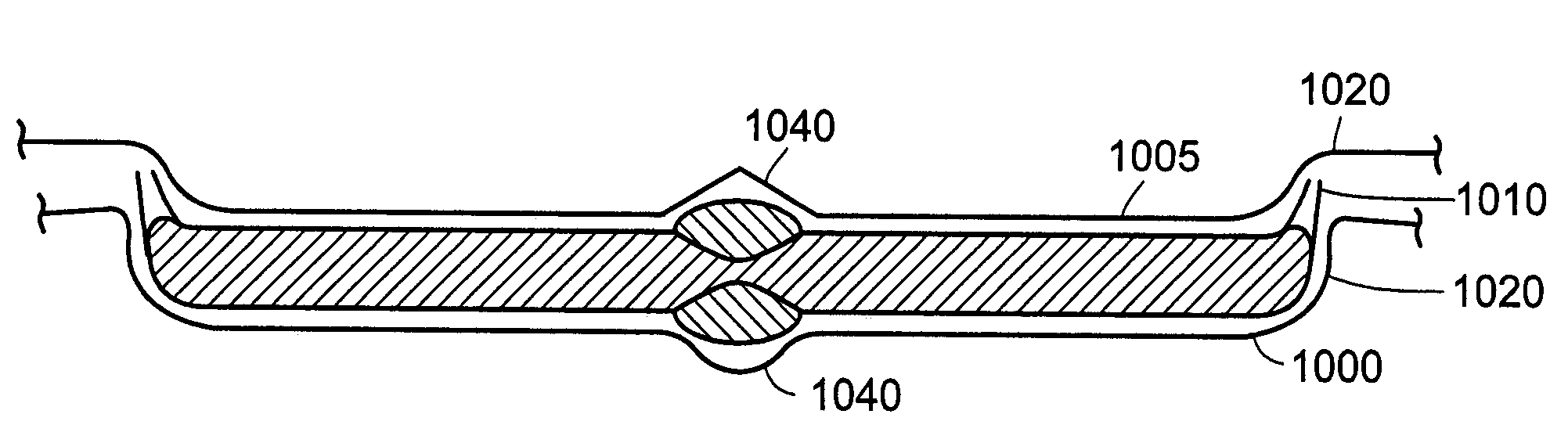
[0047]The present invention provides a composite metal article that exhibits superior bonding between the dissimilar metals. The composite metal article is formed between at least two dissimilar metals. As used herein, it is understood that the term “metals” includes metal alloys. The composite metal article is comprised of a metal base and one or more other metal elements that form a strong bond with the metal base. The bond is formed without deleteriously altering the chemical, metallurgical and / or mechanical properties of article adjacent to the bond.

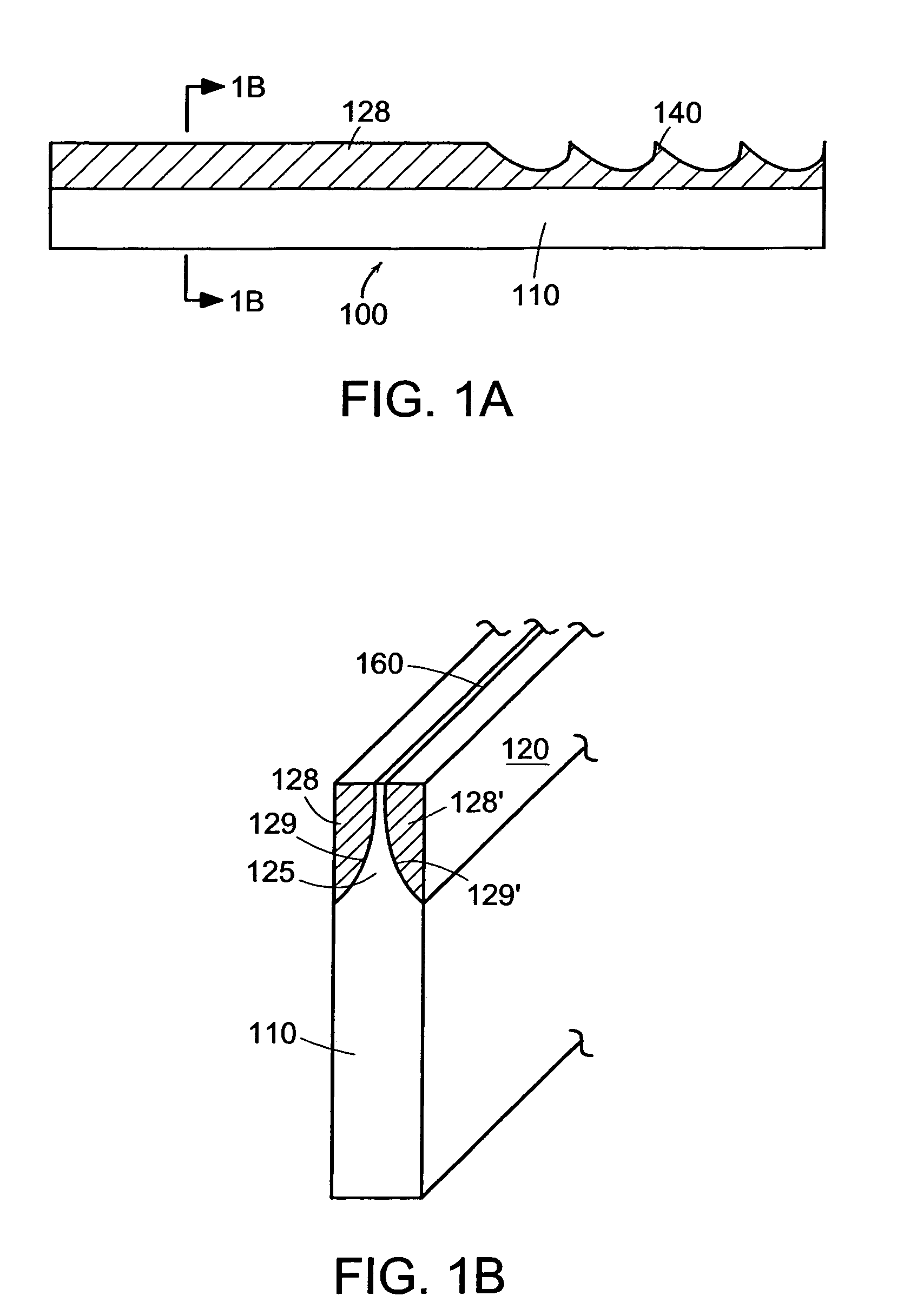
[0048]In one or more embodiments, a metal edge member is bonded on both sides of a metal base along one side of the body of the base. An exemplary composite metal article according to one or more embodiments of the invention is shown in FIGS. 1A and 1B. The article 100 includes a base 110 having a tapered edge 125 comprised of a first metal and an edge member 128 located adjacent to the tapered edge 125 of the base 110. FIG. 1A also ...


PUM

PropertyMeasurementUnit
temperaturesaaaaaaaaaa
aspect ratioaaaaaaaaaa
temperaturesaaaaaaaaaa

Abstract

A composite metal article from two dissimilar metals is prepared. A metal base is comprised of a first metal and having first and second opposing surfaces and a least one longitudinally-positioned depression in each of the first and second opposing surfaces for receiving a wire. An elongated metal element comprised of a second metal is introduced into each of the at least one first and second depressions of the metal base to form a composite assembly, and the composite assembly is heated under pressure to urge the adjacent surfaces of the second metal elements and the depressions together to form a bonded article.

Description

BACKGROUND OF THE INVENTION[0001]1. Field of the Invention[0002]This invention relates to metal articles made from dissimilar metals. It also relates to improved methods of making saw blades, and in particular, composite saw blades.[0003]2. Description of Related Art[0004]Saw bands and saw blades must have high dimensional stability of their cutting edges as well as high wear resistance. They should also be able to withstand the high loading produced by compressive, flexural and shearing forces, even under the temperatures that result from the friction between the saw blade and the material being sawn. Since it is difficult to combine the properties mentioned above in a single material, saw blade nowadays usually comprise a relatively tough metal base with high bending fatigue strength and a cutting-edge band of a high-speed steel that is less tough but highly wear resistant. The cutting-edge band is of such a width that at least the teeth tips of the saw band or blade, or even the ...

Claims


Application Information

Patent Timeline
Patent Type & Authority Patents(United States)
IPC IPC(8): B23D63/00B21B1/38B21B3/02B21B9/00B21B13/10B21B13/12B21B15/00B21B27/00B21B27/02B21B27/03B21B27/08B21B37/52B21B45/00B21K11/02B23D61/12B23D65/00B23K20/00B23K20/02B23K20/04B26B3/00B26B9/02
CPCB21K11/02B23D61/125B23D65/00B23K20/02B23K20/023B23K20/04B26B9/02B21B3/02Y10T428/1234B21B13/103B21B13/12B21B27/00B21B27/02B21B27/03B21B37/52B21B45/004B21B2001/383B21B2015/0021B21B2027/083B21B2265/06B23K2201/34B23K2203/04B23K2203/16B21B9/00B23K2101/34B23K2103/04B23K2103/16
Inventor DION, PAUL ARMANDDION, GREGG ANTHONY
Owner WILLIAM ENG LLC
Why Eureka
Try Eureka