Molding composition and method, and molded article

a technology of composition and molding, applied in the field of molding composition and method, and molded articles, can solve the problems of reduced flow, impaired moldability, and high filler levels

Inactive Publication Date: 2008-05-27
SABIC INNOVATIVE PLASTICS IP BV
View PDF111 Cites 20 Cited by
  • Summary
  • Abstract
  • Description
  • Claims
  • Application Information

AI Technical Summary

Problems solved by technology

However, higher filler levels are associated with reduced flow and impaired moldability, which are manifested as poor mold filling and increased defect generation.

Method used


Image

  • Molding composition and method, and molded article
  • Molding composition and method, and molded article
  • Molding composition and method, and molded article

Examples


examples 1-4

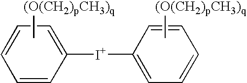
[0137]The compositions detailed in Table 1 were mixed as described above. Examples 1-3 are comparative examples. All component amounts in Table 1 are expressed in parts by weight. Example 4 is an example of the present invention. “Denka FB570 silica” is a fused silica obtained from Denka having a median particle size of 17.7 micrometers and a surface area of 3.1 meter2 / gram. “Denka SFP silica” is a fused silica obtained from Denka having a median particle size of 0.7 micrometers and a surface area of 6.2 meter2 / gram. “Yuka RSS1407LC epoxy”, obtained from Yuka Shell, is 3,3′,5,5′-tetramethyl-4,4′-diglycidyloxybiphenyl. “Sumitomo ECN-195XL-25”, obtained from Sumitomo Chemical, is an epoxidized ortho-cresol novolac resin. “OPPI” is 4-octyloxyphenyl phenyl iodonium hexafluoroantimonate available from GE Advanced Materials-Silicones as UV9392c. “OPPI O3SC4F9” is 4-octyloxyphenyl phenyl iodonium nonafluoro-n-butane sulfonate. It was prepared as follows: 50 grams of 4-octyloxyphenyl phenyl...

examples 5 and 6

[0141]The materials listed in Table 3 were mixed as described above to produce curable compositions. Example 5 is a comparative example while Example 6 is an example of the use of the present invention.

[0142]

TABLE 3IngredientExample 5Example 6Denka FB570 Silica15751429.02Denka SFP Silica175158.78Nippon Kayaku NC-3000 Epoxy Resin235.3212.44OPPI2.352.12OPPI O3SC4F901.06Benzopinacole2.352.12Carnauba Wax6.05.44Carbon Black4.03.63

[0143]Measured property values are presented in Table 4, below. These data once again demonstrate that increased spiral flows can be achieved with the mixed catalysts.

[0144]

TABLE 4TestExample 5Example 6Spiral Flow (cm) at 175° C.70.691.4Spiral Flow (cm) at 165° C.94.7112.5CTE1 (ppm / ° C.)108.7CTE2 (ppm / ° C.)3934Tg (° C.)141148Moisture Abs. (%)0.1660.209Flex Strength (MPa)130.8127.7

examples 7 and 8

[0145]The materials listed in Table 5 were mixed as described above to give curable compositions. Example 7 is a comparative example at 90% filler loading while Example 8 is an example of the use of the present invention at the same filler loading.

[0146]

TABLE 5IngredientExample 7Example 8Denka FB570 Silica16201620Denka SFP Silica180180Yuka RSS1407LC Epoxy37.3337.07Sumitomo ECN-195XL-25149.31148.3OPPI2.241.85OPPI O3SC4F900.93Benzopinacole1.121.85Carnauba Wax6.06.0Carbon Black4.04.0

[0147]Measured property values are presented in Table 6, below. Comparing spiral flow values for Example 7, with a single iodonium catalyst, and Example 8, with an iodonium catalyst mixture, shows that use of the iodonium catalyst mixture enhances spiral flow even at very high filler content.

[0148]

TABLE 6TestExample 7Example 8Spiral Flow (cm) at 175° C.41.471.4Spiral Flow (cm) at 165° C.53.885.1CTE1 (ppm / ° C.)76.1CTE2 (ppm / ° C.)2528Tg (° C.)143152Moisture Abs. (%)0.1780.209Flex Strength (MPa)130.4131.4


PUM

PropertyMeasurementUnit
softening pointaaaaaaaaaa
particle sizeaaaaaaaaaa

Abstract

A curable method useful for encapsulating solid state devices includes (A) an epoxy resin; (B) an effective amount of a cure catalyst comprising (B1) a first latent cationic cure catalyst comprising a diaryl iodonium hexafluoroantimonate salt; (B2) a second latent cationic cure catalyst comprising (B2a) a diaryl iodonium cation, and (B2b) an anion selected from perchlorate, imidodisulfurylfluoride anion, unsubstituted and substituted (C1-C12)-hydrocarbylsulfonates, (C2-C12)-perfluoroalkanoates, tetrafluoroborate, unsubstituted and substituted tetra-(C1-C12)-hydrocarbylborates, hexafluorophosphate, hexafluoroarsenate, tris(trifluoromethylsulfonyl)methyl anion, bis(trifluoromethylsulfonyl)methyl anion, bis(trifluoromethylsulfuryl)imide anion, and combinations thereof; and (B3) a cure co-catalyst selected from free-radical generating aromatic compounds, peroxy compounds, copper (II) salts of aliphatic carboxylic acids, copper (II) salts of aromatic carboxylic acids, copper (II) acetylacetonate, and combinations thereof; and (C) about 70 to about 95 weight percent of an inorganic filler, based on the total weight of the curable composition. The composition's cure catalyst allows the use of increased filler loadings, which in turn reduces moisture absorption and thermal expansion of the cured composition.

Description

BACKGROUND OF THE INVENTION[0001]Solid state electronic devices are typically encapsulated in plastic via transfer molding. Encapsulation protects the device from environmental and mechanical damage and electrically isolates the device. There are many desired technical features of encapsulant compositions. Encapsulation of wire-bonded devices requires low viscosity encapsulant injection, followed by rapid cure and hot ejection. In order to avoid damaging the solid state device, the encapsulant must not shrink excessively on curing. The encapsulated device must subsequently withstand the rigor of solder assembly onto a circuit card. The encapsulant must also be self-extinguishing in the event of a heat-producing malfunction of the circuit. And the encapsulant must adhere strongly to copper leadframes.[0002]In current epoxy-based encapsulation compositions, it is advantageous to use as much mineral filler as possible in order to decrease moisture absorption and thermal expansion of th...

Claims


Application Information

Patent Timeline
Patent Type & Authority Patents(United States)
IPC IPC(8): C08F2/50B29C39/00B29C41/00
CPCC08G59/68H01L2224/32245H01L2224/48091H01L2224/48247H01L2224/45144H01L2224/73265H01L2224/48257H01L2924/00014H01L2924/00Y10T428/31511H01L2924/00012C08L63/00C08L71/02
Inventor LU, QIWEIO'BRIEN, MICHAELVALLANCE, MICHAEL
Owner SABIC INNOVATIVE PLASTICS IP BV
Why Eureka
Try Eureka