Optical control type phased array antenna

a phased array antenna and optical control technology, applied in the direction of gain control, using reradiation, instruments, etc., can solve the problems of not taking the measures for suppressing phase noise and relative intensity noise of the light source itsel

Inactive Publication Date: 2008-06-03
MITSUBISHI ELECTRIC CORP
View PDF11 Cites 12 Cited by
  • Summary
  • Abstract
  • Description
  • Claims
  • Application Information

AI Technical Summary

Problems solved by technology

However, there is encountered a problem in that measures for suppressing a phase noise and a relative intensity noise of a light source itself are not taken in the above-mentioned conventional optical control type phased array antenna.

Method used


Image

  • Optical control type phased array antenna
  • Optical control type phased array antenna
  • Optical control type phased array antenna

Examples


embodiment 1

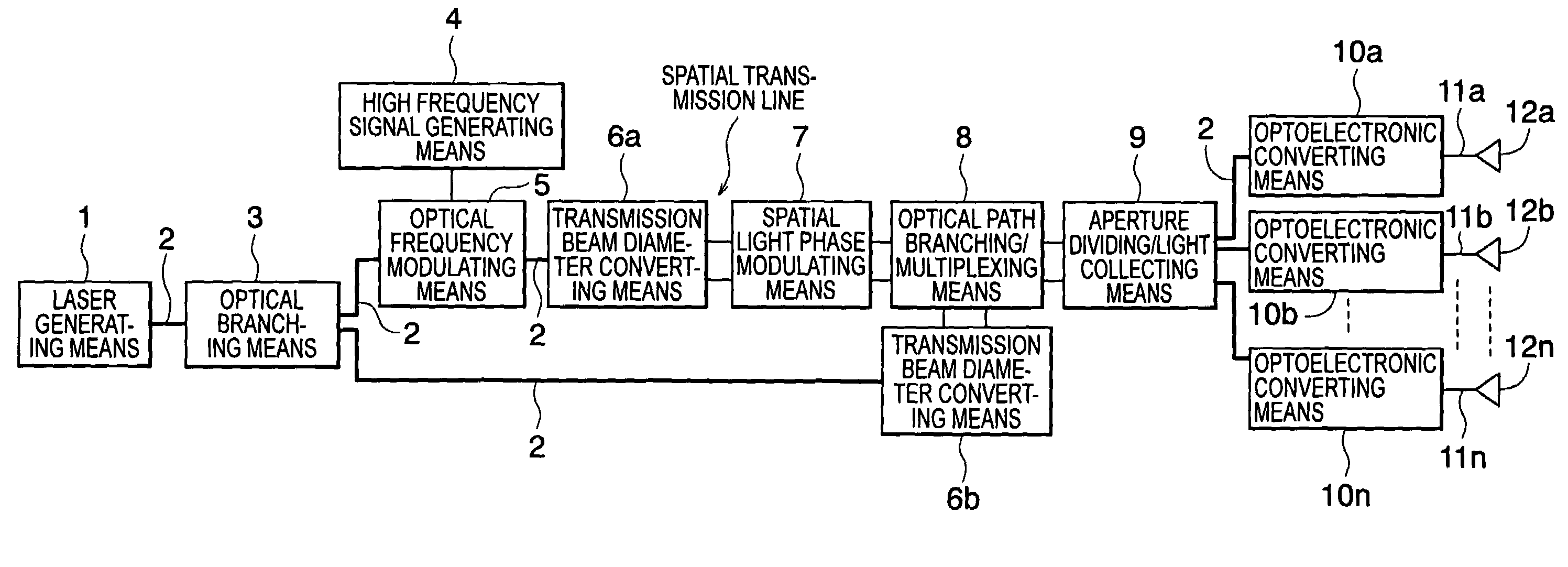
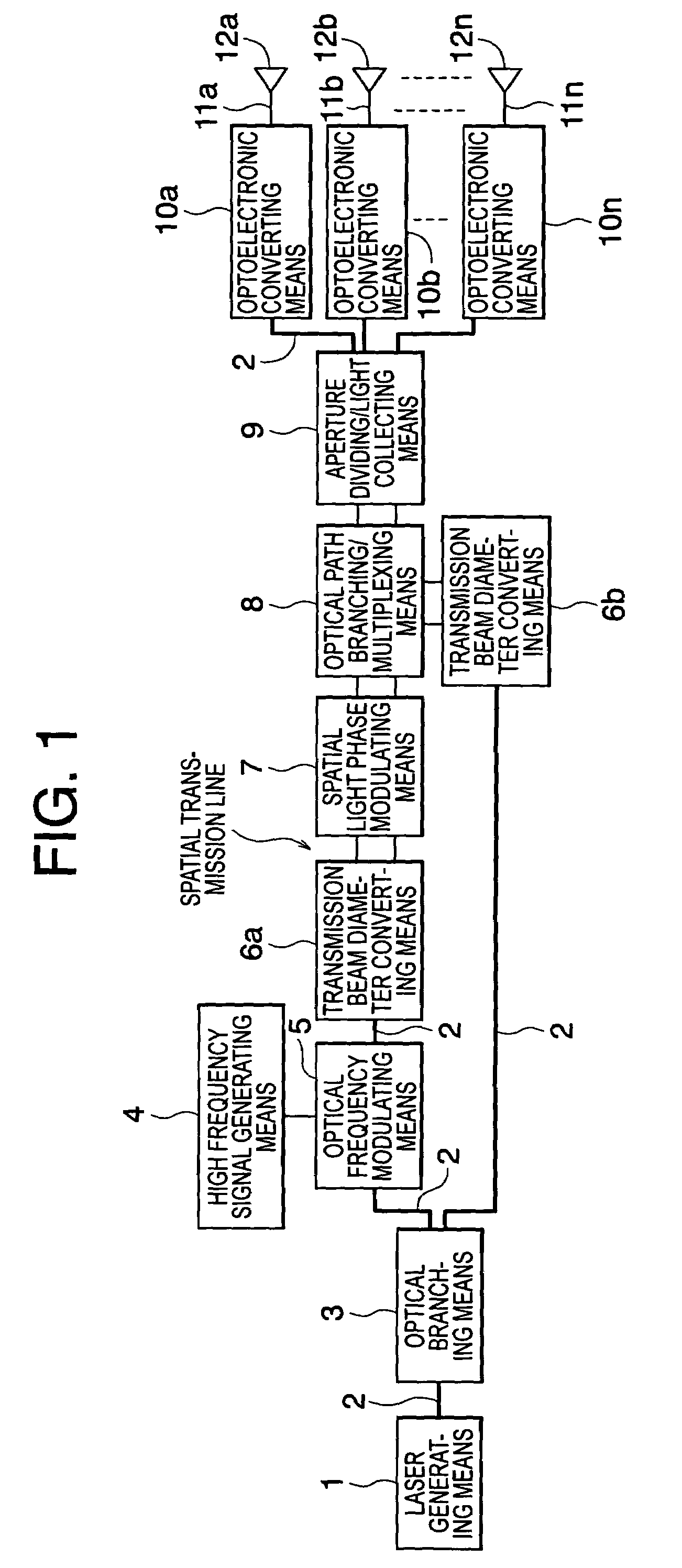
[0019]An optical control type phased array antenna according to Embodiment 1 of the present invention will now be described with reference to the corresponding drawings. FIG. 1 is a block diagram showing a configuration of an optical control type phased array antenna according to Embodiment 1 of the present invention. Note that in FIG. 1, the same reference symbols designate the same or corresponding constituent elements.

[0020]In FIG. 1, the optical control type phased array antenna includes: laser generating means 1 for generating a light having a single wavelength to output the generated light through an optical fiber; optical fiber type transmitting means (corresponding to portions indicated by heavy lines) for transmitting the light outputted by the laser generating means 1; optical path branching means 3 for branching the light transmitted through the optical fiber type transmitting means 2 and for allowing a branching ratio to be freely changed; high frequency signal generatin...

embodiment 2

[0040]An optical control type phased array antenna according to Embodiment 2 of the present invention will hereinafter be described with reference to the corresponding drawings. FIG. 4 is a block diagram showing a configuration of the optical control type phased array antenna according to Embodiment 2 of the present invention.

[0041]In Embodiment 1 described above, in the optical control type PAA, the two optical path lengths of the transmission lights obtained through the two-branching are equalized for the purpose of carrying out the heterodyne detection, thereby realizing the suppression of the phase noise with the single light source. However, when a spatial transmission line is used as the transmission means, the refractive index of the atmosphere changes due to a disturbance such as a temperature change in the space, and hence the optical path length changes. As a result, phase fluctuation is newly caused. In Embodiment 2, the suppression of the phase noise is realized using a ...

embodiment 3

[0052]An optical control type phased array antenna according to Embodiment 3 of the present invention will hereinafter be described with reference to the corresponding drawings.

[0053]In the spatial optical phase modulating means 7 shown in FIG. 4, it is possible to change the scanning direction of the beams emitted through the element antennas 12a to 12n. However, the phase shift due to the different optical path length is caused during that change as well of the beam scanning direction. In a case of a system using the PLL similarly to that of Embodiment 2, the phase difference caused by the beam direction change can also be corrected. Hereinafter, the principles thereof will be described.

[0054]Here, the phase fluctuation due to the pattern change in the spatial optical phase modulating means 7 is considered as being identical to the phase fluctuation due to the change of the scanning direction of the beams radiated through the element antennas. Then, the phase fluctuation during th...


PUM

PropertyMeasurementUnit
single wavelengthaaaaaaaaaa
frequencyaaaaaaaaaa
light intensitiesaaaaaaaaaa

Abstract

An optical control type phased array antenna includes a laser generating means for generating light of single wavelength, an optical path branching means for branching the light emitted from the laser generating means into first and second transmission lights, a high frequency signal generating means for generating a high frequency signal, an optical frequency modulating means for shifting the frequency of the first transmission light branched by the optical path branching means by the frequency of a high frequency signal thus generated, a spatial light phase modulating means performing spatial phase modulation of the first transmission light shifted by the frequency of a high frequency signal depending on the antenna beam pattern, and an optical path branching / multiplexing means for multiplexing the first transmission light subjected to phase modulation and the second transmission light branched by the optical path branching means. Optical path lengths of two paths between the optical path branching means and the optical path branching / multiplexing means are equalized.

Description

TECHNICAL FIELD[0001]The present invention relates to an optical control type phased array antenna (PAA) capable of suppressing a phase noise and a relative intensity noise.BACKGROUND ART[0002]A conventional optical control type phased array antenna includes signal generating means for outputting one electrical signal corresponding to an inputted beam direction of a phased array antenna, and a plurality of phase shifting means for phase-shifting a plurality of first optical signals outputted from second distribution means by phase amounts which correspond to the electrical signal and which are different from one another. Thus, a circuit can be simplified to be reduced in size and weight, and hence the whole phased array antenna including the circuit can be reduced in size and weight (refer to JP-A 3-57305 (page 9 and FIG. 1) for example).[0003]However, there is encountered a problem in that measures for suppressing a phase noise and a relative intensity noise of a light source itsel...

Claims


Application Information

Patent Timeline
Patent Type & Authority Patents(United States)
IPC IPC(8): H04B10/00H01Q1/06H04B10/04H04B10/12G02F1/01G02F2/02H01Q3/26H01Q3/30H03G3/26
CPCH01Q3/2676
Inventor MIZUMA, MASASHIANDO, TOSHIYUKIAKIYAMA, TOMOHIROHIRANO, YOSHIHITO
Owner MITSUBISHI ELECTRIC CORP
Why Eureka
Try Eureka