
Substrate processing method, substrate processing apparatus and substrate processing system

Inactive Publication Date: 2008-06-10
DAINIPPON SCREEN MTG CO LTD +1
View PDF21 Cites 18 Cited by
  • Summary
  • Abstract
  • Description
  • Claims
  • Application Information

AI Technical Summary

Benefits of technology

[0015]A primary object of the invention is to provide a substrate processing method permitting a sequence of processes from the wet process to the drying process to be favorably performed without causing damages such as the fine pattern collapse to the substrate, and a substrate processing apparatus and a substrate processing system suited for the method.
[0016]Another object of the invention is to provide a substrate processing apparatus which is small and less expensive but has high versatility.
[0020]The high-pressure fluid used in the present invention is preferably carbon dioxide because of its safety, price and easiness of changing into a supercritical state. Other than carbon dioxide, water, ammonia, nitrogen monoxide, ethanol or the like may be used. The reasons why the high-pressure fluid is used are as follows. The high-pressure fluid has a high diffusion coefficient so that it is possible to disperse a dissolved contaminant into a medium. In addition, when the high-pressure fluid is changed into a supercritical fluid by bringing higher pressure thereon, it is possible to more penetrate even through fine patterns due to its property between gas and liquid. Further, density of the high-pressure fluid is close to that of liquid so that it is possible to contain a far larger amount of an additive (chemical agent) in comparison with gas.

Problems solved by technology

In recent years, the semiconductor devices have been speeding toward fine structure which has raised new problems in the substrate processing field.
As a consequence, the performance of the supercritical drying means nothing.
Unfortunately, the aforesaid substrate processing apparatus including the developing unit, the high-pressure processing unit and the transport robot takes only the alkaline developing process into consideration, thus suffering poor versatility.
However, such a substrate processing apparatus provided with the special transport units (the alkaline-development transport robot and the organic-development transport robot) corresponding to the individual developing contents is detrimentally increased in size and costs.
However, the following problem is encountered by the conventional apparatus wherein the wet process and the high-pressure drying process are sequentially performed in a single reactor.
The most crucial one of the limiting conditions is that the range of selection of the processing fluid is limited.
Where a corrosive processing fluid of strong acid or strong alkali is used for carrying out the surface treatment, the processing fluid corrodes a liquid contacting surface of the pressure container.
On this account, a corrosive chemical agent of strong acid or alkali cannot be introduced in the pressure container for carrying out the surface treatment.
However, it is actually impossible to ensure that the anti-corrosive coating continues to exhibit its function over an extended period of time under the high pressure condition.

Method used


Image

  • Substrate processing method, substrate processing apparatus and substrate processing system
  • Substrate processing method, substrate processing apparatus and substrate processing system
  • Substrate processing method, substrate processing apparatus and substrate processing system

Examples


first embodiment

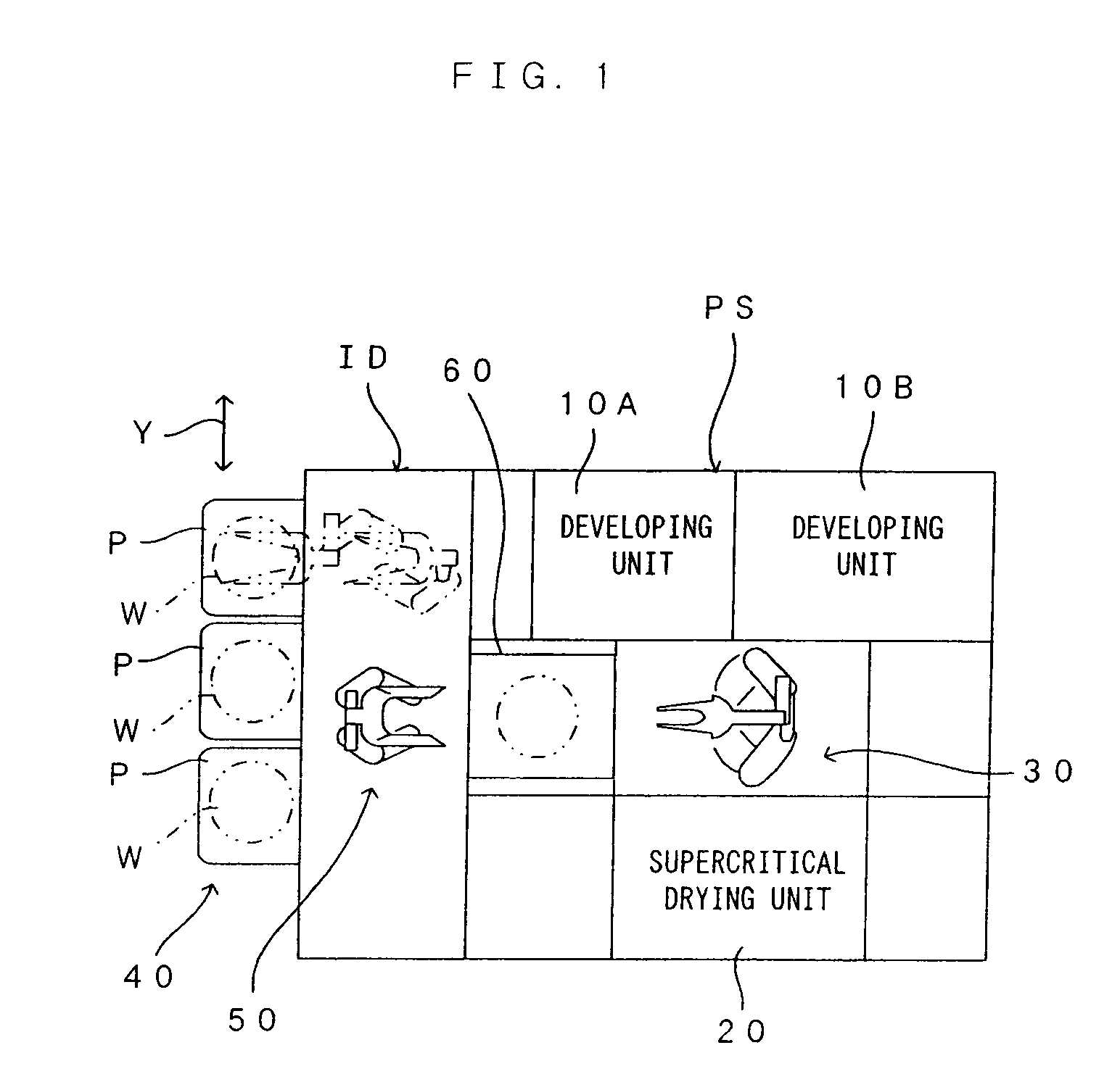
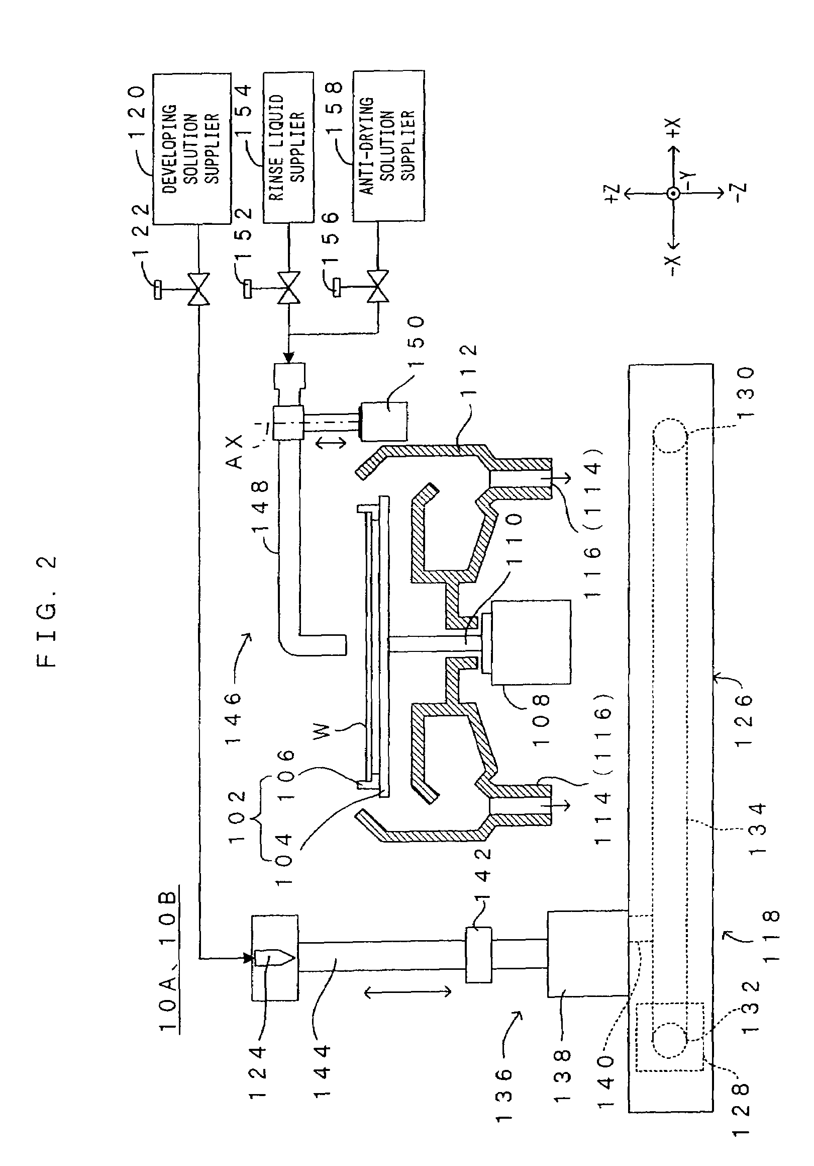
[0036]FIG. 1 is a diagram showing a substrate processing system according to a first embodiment of the present invention. FIG. 2 is a diagram showing a developing unit installed in the substrate processing system of FIG. 1. FIG. 3 is a diagram showing a high-pressure drying unit installed in the substrate processing system of FIG. 1. As shown in FIG. 1, the substrate processing system includes a substrate processing section PS and an indexer ID connected with the substrate processing section PS.

[0037]The substrate processing section PS is provided with a plurality of developing units (two developing units 10A, 10B provided in this embodiment) which each performs the same wet process to a substrate. The developing units are defined as a “wet processing apparatus”, a “substrate processing apparatus” or a “wet processing unit” of the present invention. Specifically, each of the developing units 10A, 10B supplies a developing solution, as a first processing fluid, to a surface of a subs...

second embodiment

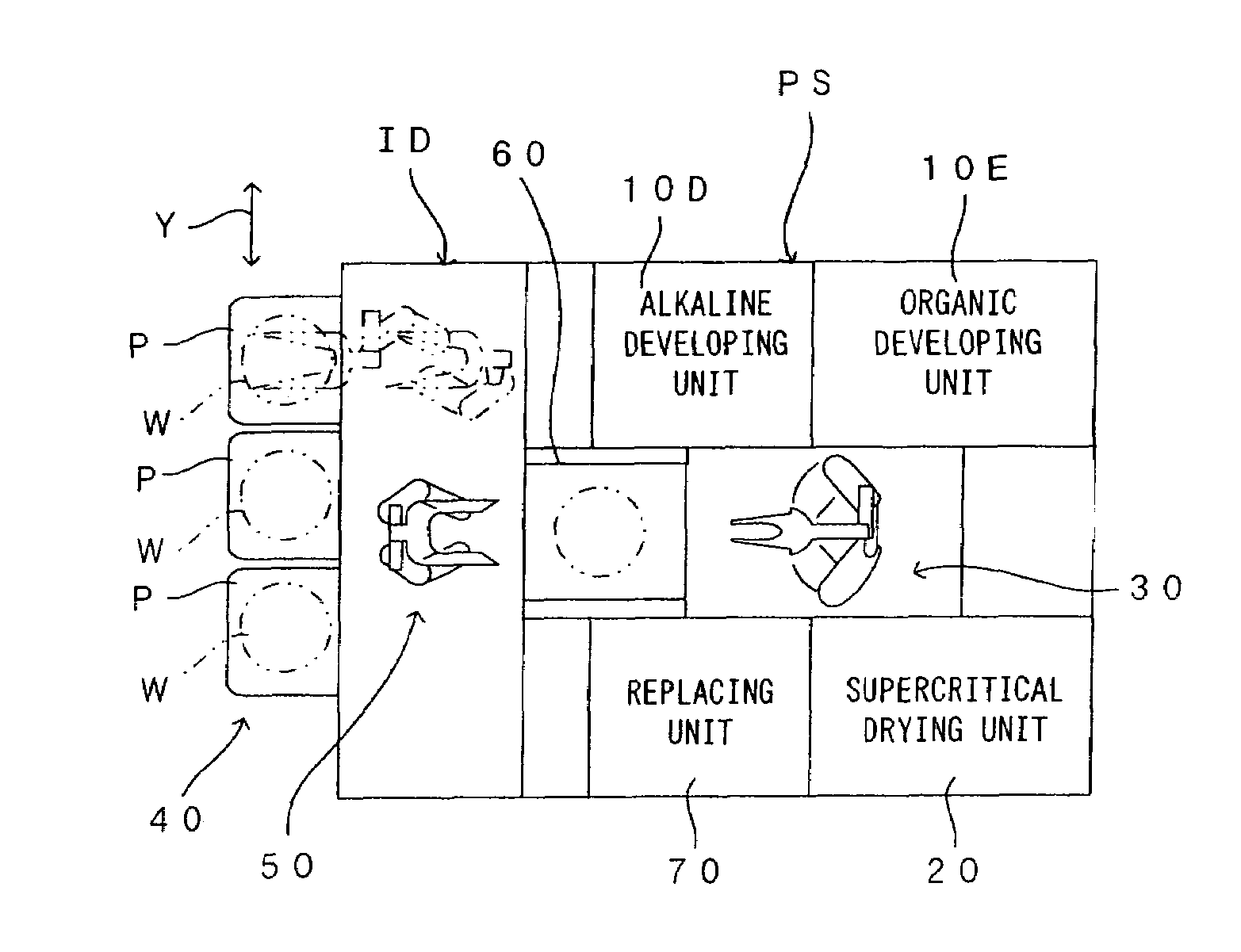
[0069]FIG. 6 is a diagram showing a substrate processing system according to a second embodiment of the present invention. In the second embodiment, a major difference from the first embodiment is as follows. That is, the developing units 10A, 10B in the substrate processing section PS according to the first embodiment perform the same wet processes on the substrate, whereas the developing units according to the second embodiment perform different developing processes, respectively. The developing units 10A, 10B are essentially constructed the same way as those of the first embodiment. However, these developing units use different developing solutions and rinse liquids, respectively. Hereinafter, therefore, the same components will be represented by the same reference characters, respectively, the description of which will be dispensed with. The following description will be made focusing on the difference.

[0070]Although both the developing units 10A, 10B are supplied with a common ...

third embodiment

[0089]FIG. 8 is a diagram showing a substrate processing system according to a third embodiment of the present invention, whereas FIG. 9 is a diagram showing a developing unit installed in the substrate processing system of FIG. 8. FIG. 10 is a diagram showing a replacing unit installed in the substrate processing system of FIG. 8. In the third embodiment, a major difference from the first embodiment is as follows. That is, the developing process, rinsing process and replacing process are performed in the same developing unit 10A or 10B according to the first embodiment, whereas the third embodiment is arranged such that the developing process and rinsing process are performed in a developing unit 10C and the replacing process is performed in a dedicated replacing unit 70. Furthermore, the primary transport robot 30 wet-transports a substrate W from the developing unit 10C to the supercritical drying unit 20 via the replacing unit 70. The other features are essentially the same as t...


PUM

PropertyMeasurementUnit
Currentaaaaaaaaaa
Digital informationaaaaaaaaaa
Pressureaaaaaaaaaa

Abstract

After subjected to a developing process, a rinsing process and a replacing process in this order in a developing unit 10A, 10B, a substrate W wet with an anti-drying solution is wet-transported to a supercritical drying unit 20 by a primary transport robot 30. The supercritical drying unit 20 performs a high-pressure drying process (supercritical drying process) in a dedicated manner. Accordingly, by virtue of the presence of the anti-drying solution, the substrate W is effectively prevented from becoming air-dry during the transportation of the substrate W.

Description

BACKGROUND OF THE INVENTION[0001]1. Field of the Invention[0002]The present invention relates to a substrate processing method of performing sequential processes from a predetermined wet process to a drying process on a variety of substrates such as semiconductor wafers, glass substrates for photomask, glass substrates for liquid crystal display, glass substrates for plasma display, optical disk substrates (hereinafter, simply referred to as “substrate”), as well as to a substrate processing apparatus and a substrate processing system suited for such a method.[0003]2. Description of the Related Art[0004]In recent years, the semiconductor devices have been speeding toward fine structure which has raised new problems in the substrate processing field. In a case where a fine pattern is formed by patterning a resist applied on a substrate, for example, a wet developing process and a drying process are performed in this order. In the wet developing process for developing the resist appli...

Claims


Application Information

Patent Timeline
IPC IPC(8): B05C13/00B05C13/02B05B1/26B05B7/00B08B3/00C23C14/00G11B7/26H01L21/00H01L21/677
CPCH01L21/67028H01L21/67051G11B7/261G11B7/265Y10S134/902
Inventor MURAOKA, YUSUKESAITO, KIMITSUGUIWATA, TOMOMIFUKATSU, EIJIMIZOBATA, IKUOUENO, HIROYUKIOKUYAMA, YASUOGAMA, TAKASHISAKASHITA, YOSHIHIKOWATANABE, KATSUMIMUNEMASA, JUNOSHIBA, HISANORISARUMARU, SHOGO
Owner DAINIPPON SCREEN MTG CO LTD
Learn More