Braze alloys

a technology of alloys and brazing, applied in the direction of welding/cutting media/materials, manufacturing tools, soldering apparatus, etc., can solve the problem of relatively low joint strength of soldering, and achieve the effect of improving at least one characteristi

Inactive Publication Date: 2008-06-24
SMITH INT INC
View PDF22 Cites 47 Cited by
  • Summary
  • Abstract
  • Description
  • Claims
  • Application Information

AI Technical Summary

Benefits of technology

[0011]The present invention relates to metal alloys useful as brazing material. In accordance with embod

Problems solved by technology

Soldering offers relatively low joint strength for meta

Method used


Image

  • Braze alloys
  • Braze alloys
  • Braze alloys

Examples


examples

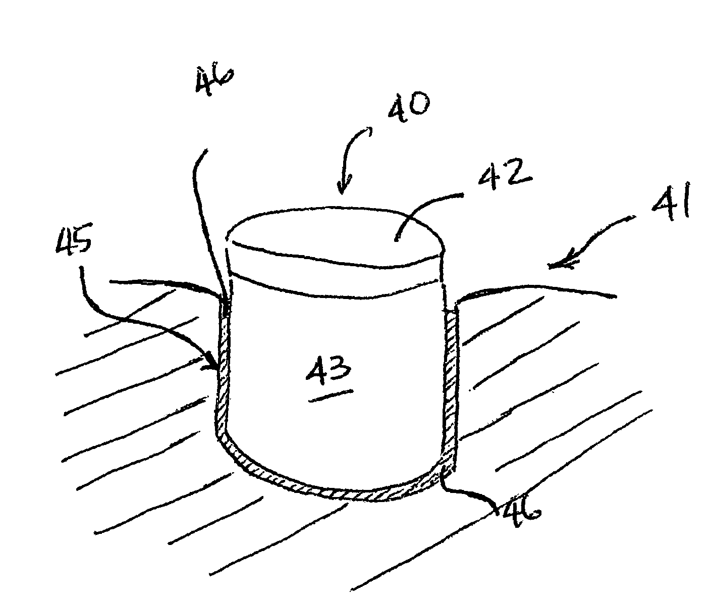
[0043]One example of a brazing application in which a brazing material is desired which offers improved brazing characteristics is the brazing of PCD cutters to bit bodies. This type of application is a temperature sensitive application. Thus it is desired that the characteristics of the brazing material be improved while maintaining braze temperature at a value at or below 1400° F. to avoid damage to the PCD table of the PCD cutter.

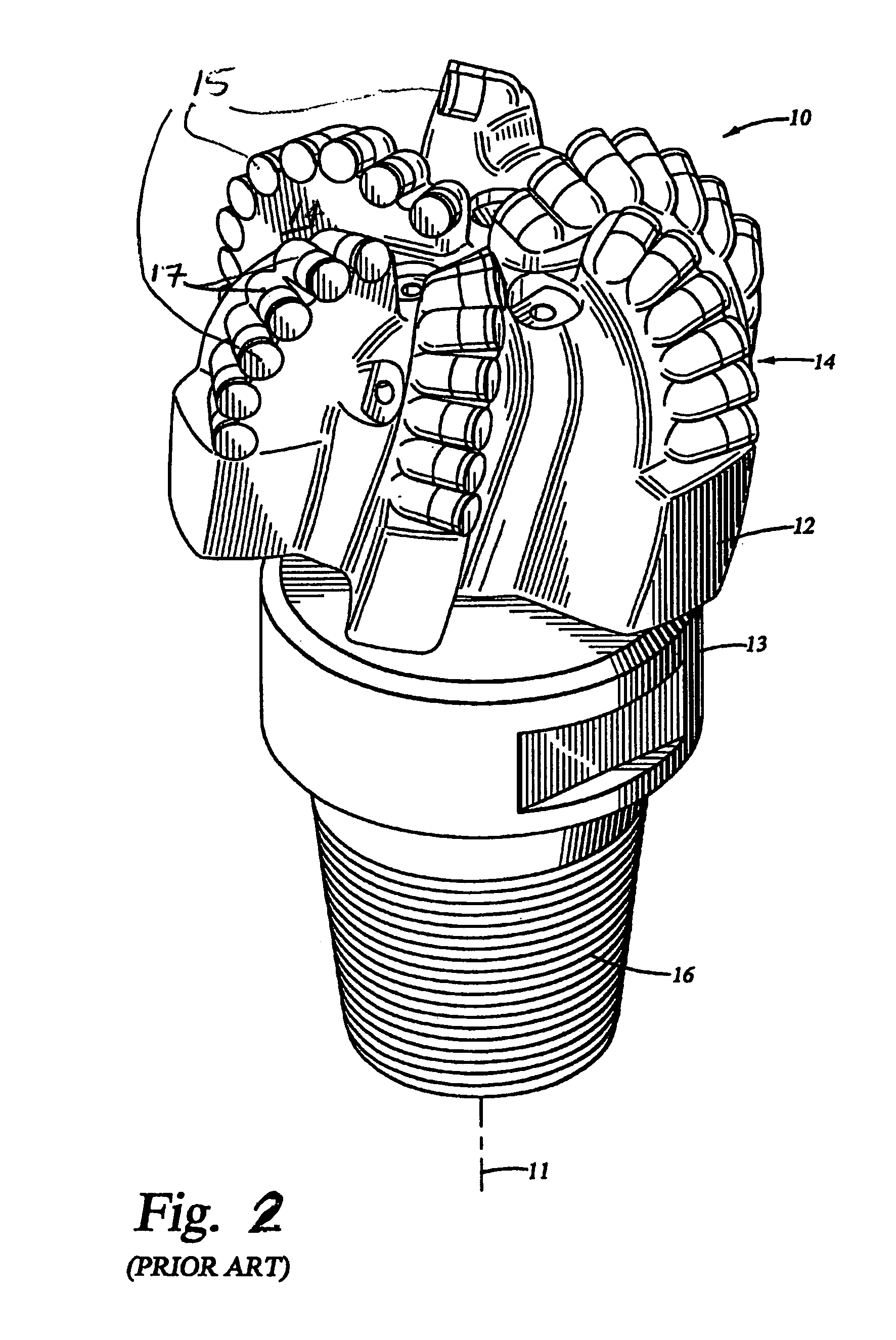
[0044]FIG. 2 shows one example of a fixed-cutter drill bit used for drilling bore holes in subterranean earth formations. The fixed-cutter bit 10 includes a bit body 12 having a threaded connection 16 at one end for connecting to a drilling assembly, and blades 14 extending from the other end. The bit body may be formed of a matrix material infiltrated with binder materials to form the body or a machined steel body. Polycrystalline diamond compact (PDC) cutters 15 are mounted in cutter pockets 17 on the blades 14 and bonded to the cutter pockets 17 by br...


PUM


Abstract

An improved braze alloy is microalloyed to include about 0.0005 wt % to about 0.5 wt % of at least one aggressively surface acting element selected from tellurium (Te), selenium (Se), antimony (Sb), bismuth (Bi), and gallium (Ga), or any combination thereof. The braze alloys may include at least about 30% by weight of at least one base metal selected from the group of silver (Ag), copper (Cu), gold (Au), nickel (Ni), or aluminum (Al). In one example, a silver braze alloy suitable for brazing a cutter to a drill bit body is microalloyed to improve a characteristic of the braze material.

Description

CROSS-REFERENCE TO RELATED APPLICATIONS[0001]This application claims priority, pursuant to 35 U.S.C. §119(e), to U.S. Provisional Patent Application Ser. No. 60 / 506,871, filed Sep. 29, 2003, which is incorporated herein by reference in its entirety.STATEMENT REGARDING FEDERALLY SPONSORED RESEARCH OR DEVELOPMENT[0002]Not applicable.BACKGROUND OF INVENTION[0003]1. Field of the Invention[0004]The present invention relates to brazing material. More particularly, the present invention relates to a brazing material that is microalloyed to improve a characteristic of the brazing material.[0005]2. Background Art[0006]Base metals, including metals and metal alloys, can be joined in a number of different ways, such as by mechanical fastening, adhesive bonding, or using heat and a filler material to join the metals together. Metal joining techniques involving heat and filler materials are separated into three distinct classes known as soldering, brazing, and welding.[0007]Soldering is a relati...

Claims


Application Information

Patent Timeline
IPC IPC(8): E21B10/567
CPCB23K35/3006E21B10/56
Inventor KEMBAIYAN, KUMAR T
Owner SMITH INT INC
Why Eureka
Try Eureka