Device and method for the determination of the quality of surfaces

a technology of surface quality and device, which is applied in the direction of material analysis, instrumentation, spectral investigation, etc., can solve the problems of only being able to correct the spectral distribution caused by deposits on the inside of the glass body of the light bulb, affecting affecting the quality of the surface. , to achieve the effect of improving the reproducibility and precision of surface quality measurement, reducing cycle duration, and increasing the frequency of measuremen

Inactive Publication Date: 2008-06-24
BYK GARDNER
View PDF42 Cites 50 Cited by
  • Summary
  • Abstract
  • Description
  • Claims
  • Application Information

AI Technical Summary

Benefits of technology

[0023]A decisive advantage of the invention is that the position of the light source as well as the light-emitting surface and the amount of emitted light is precisely defined with respect to the device. With conventional light or halogen bulbs and the like, the member which emits light is the filament, which is usually held in place in the glass body of the light bulb by means of thin wires. This type of spring-like suspension has the effect that even minor shaking or vibration can induce changes in the position of the light-emitting source, the filament respectively. Thus an exact determination or prognosis of the intensity and direction of the propagated radiation is only possible with considerable effort, if at all.
[0024]In contrast thereto, by employing an LED as the light source, the position of the light-emitting member, the light-emitting surface respectively, is defined precisely and does not vary over time, even due to factors contingent upon aging. This substantially improves the reproducibility and precision of the measurement of surface quality.
[0025]Also advantageous is that using an LED as light source when determining a parameter allows for an increased frequency of measurement, respectively a reduced cycle duration. The light sources in present known devices are usually turned off, only to be turned on at the time of measurement, in order to reduce internal scattered light within the device. While a typical light bulb requires at least 1 to 1.5 seconds to attain an essentially stable emission of radiation, the comparable timeframe for a light-emitting diode amounts to only about 0.1 to 0.2 seconds, sometimes even less. It follows that the measurement frequency can be increased by a factor of approximately 7 to 15. A measurement cycle when employing an LED typically takes less than 0.2 seconds, while approximately 1.5 to 2 seconds are required when utilizing a light bulb.
[0026]Another advantage of a device according to the present invention is that contingent upon the spectral characteristic of the light source, preferably exhibiting at least blue, green and red spectral components in the visible spectrum, the surface is illuminated with different wavelengths and the surface parameters to be measured can be reliably determined.
[0027]As the light-emitting source according to the present invention is subject to only minor age-contingent changes to the emitted spectrum, the daily calibration necessary with conventional devices is no longer necessary. With the device according to the present invention, it is sufficient to carry out an occasional calibration using a measurement standard, for example twice a year. Should measurements frequently be conducted under dusty or dirty conditions, it may be sensible to increase the frequency of calibration in order to curb the influences of dirt and dust which settle or deposit on the optic elements employed.
[0028]A reduced frequency of recalibration for a device in accordance with the present invention is extremely advantageous since, in addition to saving time, possible errors which might occur during the recalibration process are avoided. This includes operator errors as well as faulty calibration standards such as, for example, those which are contaminated or damaged.

Problems solved by technology

A disadvantage with using such light sources is that the filament ages and part of it vaporizes, whereby the vaporized material characteristically builds up deposits on the inside of the filament's surrounding glass body.
A further disadvantage of such conventional light sources is that the position of the filament can change over time due to the effects of aging or due to jarring impacts to the device.
A correction of the spectral distribution caused by deposits on the inside of the light bulb's glass body is only possible, however, by replacing the light source which then further entails having to accept other spectral differences, for example those induced by technical production contingencies.
Another disadvantage of such measuring devices employing conventional irradiation sources is their low measuring frequency and also the length of time which is required after switching on the device before one can render a usable measurement result, as conventional light bulbs require a relatively long period of time before they are able to emit a stable and reproducible spectral radiation.
When attempting to ascertain a surface gloss measurement, should said surface be illuminated with a monochromatic light source such as a laser, for example, this results in the disadvantage that the gloss, respectively the reflection capacity, is then determinable solely for the illuminated wavelength.
A monochromatic illumination thus has the disadvantage that nominally identical gloss, color or similar characteristics are determined from different surfaces although the physiologically perceptible parameters clearly differ.

Method used


Image

  • Device and method for the determination of the quality of surfaces
  • Device and method for the determination of the quality of surfaces
  • Device and method for the determination of the quality of surfaces

Examples


first embodiment

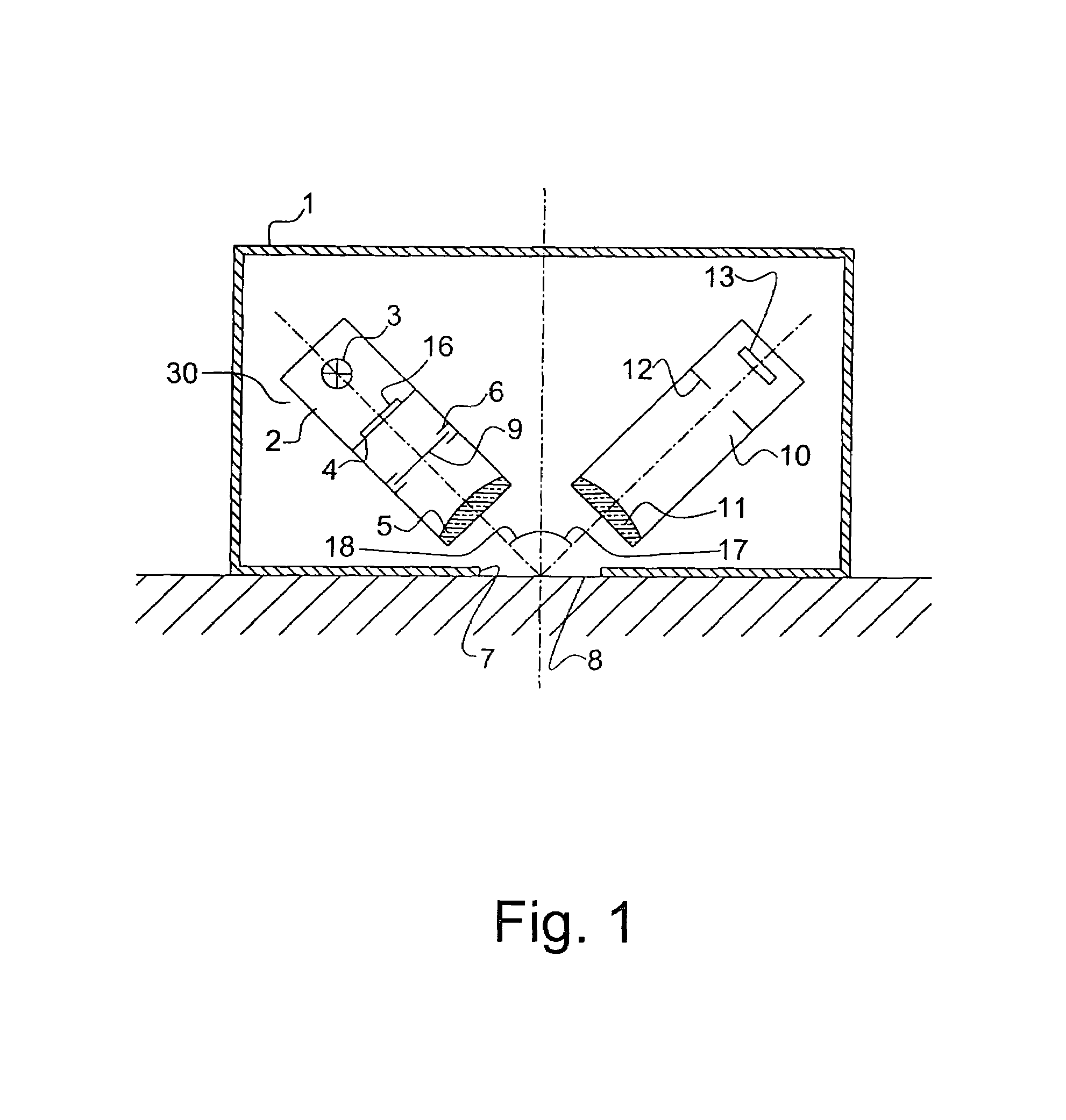
[0113]the present invention will now be described with reference to FIGS. 1-5.

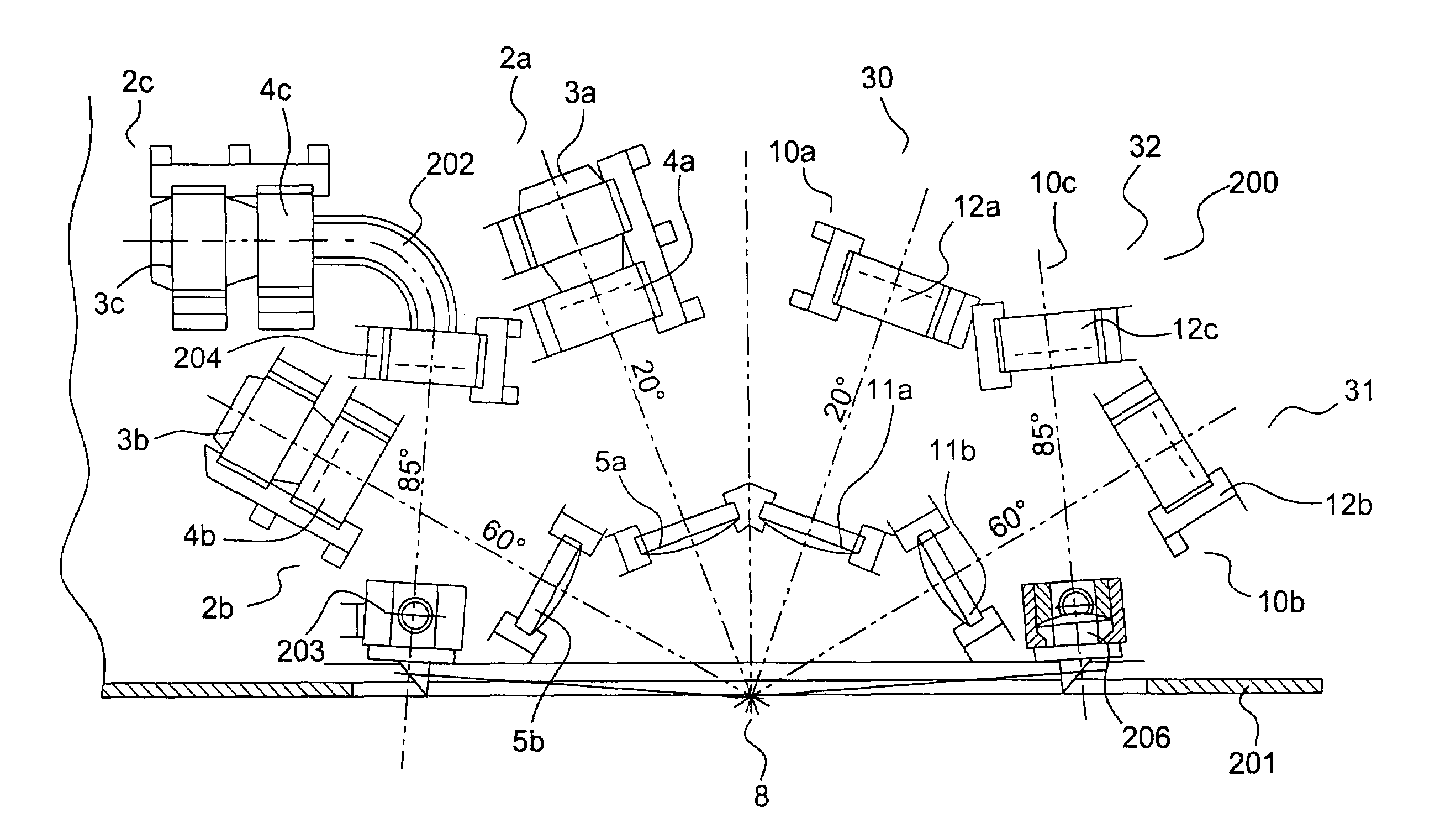
[0114]The measuring device for determining the quality of surfaces represented sectionally in FIG. 1 has a housing 1 with an opening 7 provided therein. The device is placed with opening 7 on measurement surface 8. A first optical system 30 is arranged within the device which comprises a first optical means 2 and a second optical means 10.

[0115]The optical axes of both optical means 2, 10 are arranged at angles 17, 18 to the vertical of measurement surface 8. In this embodiment, angles 17, 18 have been selected to be symmetrical and amount to 45°. As a variation of the device, and especially for gloss measurements, an angle of 60° is preferred.

[0116]In first optical means 2, a light source 3 is disposed which is configured as a light diode and its emitted spectrum essentially exhibits intensity throughout the entire visible range.

[0117]The light radiated from light diode 3 impinges upon scatter disk 16, wh...


PUM

PropertyMeasurementUnit
reflection anglesaaaaaaaaaa

Abstract

The present invention relates to a device and method for making quantified determinations of the quality of surfaces and wherein the device comprises an optical system with a first optical means and a second optical means as well as a control and evaluation means and an output (display) means. Said first optical means comprises an illuminating means having at least one LED as its light source and serves the function of illuminating the measurement surface at a predetermined angle. Said second optical means is likewise directed at a predetermined angle to the measurement surface and receives the reflected light. A photo sensor of said second optical means emits an electrical measurement signal which is characteristic of said reflected light.The light emitted from the illuminating means is configured such that its spectral characteristic comprises blue, green and red spectral components in the visible light spectrum. A filter means is arranged in the path of radiation between the light source and the photo sensor and which changes the spectral characteristics of the incident light so as to approach a predetermined spectral distribution. The control and evaluation means control the measurement sequence and evaluate the reflected light, deriving therefrom at least one parameter which is characteristic of the surface.

Description

FIELD OF THE INVENTION[0001]The present invention relates to a device and method for determining the quality of surfaces, respectively visual properties of surfaces.DESCRIPTION OF RELATED ART[0002]The quality of a surface, respectively its visual properties, is to be understood as those physical characteristics which determine the appearance of the surface for a human observer. The characteristics which in particular distinguish the quality of a surface include gloss, haze, distinction of image (DOI), color brightness, surface texture and surface ripples (orange peel), etc.[0003]These parameters constitute important criteria involved in the determination of the quality of a surface such as, for example, the quality of finished, synthetic or metallic surfaces, since the nature of visible surface properties is a decisive characteristic for the overall appearance in numerous technical components and products. A typical example of products of this kind are automobile bodies; the structu...

Claims


Application Information

Patent Timeline
Patent Type & Authority Patents(United States)
IPC IPC(8): G01N21/00G01B11/30G01N21/47G01N21/55G01J3/10G01J3/12G01J3/28G01J3/51G01N21/25G01N21/57
CPCG01B11/30G01J3/10G01J3/51G01N21/255G01J3/2803G01J3/465G01J3/501G01J2003/1282
Inventor SCHWARZ, PETERSPERLING, UWE
Owner BYK GARDNER
Why Eureka
Try Eureka