
Spread spectrum communication method and system using diversity correlation and multi-user detection

Active Publication Date: 2008-06-24
S AQUA SEMICONDUCTOR LLC
View PDF6 Cites 77 Cited by
  • Summary
  • Abstract
  • Description
  • Claims
  • Application Information

AI Technical Summary

Benefits of technology

[0010]Diversity parameters of received signals can be adjusted by either or both the transmitters and the receivers. This ensures separability of interfering signals and enables optimization of the correlation process. A related objective of the invention is to optimize the correlation process by adjusting either or both the receivers and the transmitters.
[0011]Correlation processing at antenna arrays allows a small number of antenna elements to separate a large number of unknown signals. Long Baseline Interferometry may be used to increase the number of resolvable signals that can be processed by the array. Consequently, an objective of the invention is to reduce the number of antenna elements needed for array processing of spread-spectrum signals.
[0012]A communication channel may be used to adjust diversity parameters of the transmitted signals. Thus, another objective of the invention is to exploit distortion (such as multipath effects) in a communication channel to enhance signal quality and increase system capacity for spread-spectrum communications. Different communication channels, including communication channels associated with co-located transceivers, can provide distinct variations to diversity parameters of transmitted signals. For example, signals may change with respect to polarization, delay spread, spatial gain distribution, directional gain distribution, frequency-dependent gain distribution, mode distribution, phase space, etc. These variations can be used as unique signatures to identify signals received from different transmitters. There are many preferred methods, including correlation, that may be used to separate signals transmitted by different transmitters.
[0013]The correlation process may be combined with multi-user detection that removes interference and noise in a spread-spectrum receiver. Multi-user detection includes cancellation and constellation techniques that provide multiple algebraically unique combinations of unknown signals (including desired signals, interference, and noise). The objective of multi-user detection is to separate interfering signals in order to optimize signal-to-noise, signal-to-interference, or signal-to-noise-plus-interference ratios. Thus, an objective of the invention is to improve frequency reuse in a spread-spectrum communication system.
[0014]Further objectives of the invention include using true noise sources to encode information signals in a spread-spectrum communication system and simplifying receiver designs. An additional objective is to provide a bandwidth-efficient means of transmitting a decoding signal along with an information-modulated spread spectrum signal. This objective serves to simplify the receiver design, enable the transmitter to use spreading codes and noise-like signals that do not need to be duplicated by the receiver, and overlay a decoding signal in the same frequency band as its associated coded information signal.

Problems solved by technology

These methods are complex processes and are more difficult to implement than tracking users in non-CDMA systems.
These changes may be the major obstacle for adaptive array deployment in the near future.
However, phase-based electronically controlled phased-array systems are relatively large, heavy, complex, and expensive.
This arrangement results in a system that is relatively lossy, electromagnetically sensitive, hardware-intensive, and has a narrow tunable bandwidth.

Method used


Image

  • Spread spectrum communication method and system using diversity correlation and multi-user detection
  • Spread spectrum communication method and system using diversity correlation and multi-user detection
  • Spread spectrum communication method and system using diversity correlation and multi-user detection

Examples


Embodiment Construction

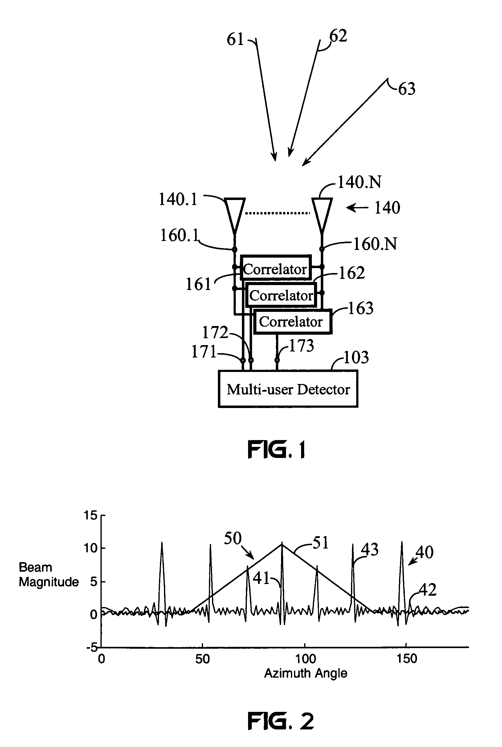
[0051]FIG. 1 shows a spread-spectrum receiver system of the present invention. An array 140 including at least two receivers 140.1 and 140.N receives a plurality of signals sn(t) from a plurality of directions of arrival, such as directions 61, 62, and 63, in a communication channel (not shown). Different directions (such as directions 61, 62, and 63) of arrival result in a plurality of different signal delays Δti occurring between signals received by the two receivers 140.1 and 140.N. Signal responses of the receivers 140.1 and 140.N are output at one or more receiver outputs, such as outputs 160.1 and 160.N. The receiver-output signals are coupled into a plurality of correlators 161, 162, and 163. The output of each correlator 161, 162, and 163 is coupled to a multi-user detector 103.

[0052]Three transmitted signals s1(t), s2(t), and s3(t) arrive at the array 140 from the directions 61, 62, and 63, respectively. This simple case is shown for the purpose of facilitating an understan...


PUM


Abstract

A communication system transmits and receives a plurality of spread-spectrum signals having differences in at least one diversity parameter. The signals are highly correlated when their diversity parameters are similar, and the signals are uncorrelated when at least one diversity parameter is different. Any combination of a transmitter, a receiver, and a communication channel may diversity-encode the signals to effect differences in their diversity parameters. A receiver diversity-decoder compensates for differences in a diversity-parameter of at least one received signal to make the signal highly correlated with at least one other received signal. A correlator combines at least two of the received signals to recover an embedded information signal. The communication system enables the use of true-noise signals for spreading information signals, provides simplified receiver designs, and enables antenna arrays to spatially process spread-spectrum signals.

Description

[0001]This application claims the benefit of U.S. provisional application Ser. No. 60 / 194,633, Filed Apr. 4, 2000.FIELD OF THE INVENTION[0002]The present invention relates to spread-spectrum communication and radar systems. More specifically, the present invention relates to a spread-spectrum communication system that uses a diversity-processing system, such as an antenna array.BACKGROUND OF THE INVENTION[0003]In a spread-spectrum communication system, the transmitted signal bandwidth is much greater than the bandwidth or rate of information being sent. Also, some function other than the information being sent is employed to provide the resulting modulated radio-frequency (RF) bandwidth.[0004]The desired signal is recovered by remapping the expanded-bandwidth signal into the original information bandwidth. In direct sequence CDMA (DS-CDMA) systems, removal or demodulation of the spectrum-spreading modulation is accomplished by multiplication with a local reference identical in struc...

Claims


Application Information

Patent Timeline
IPC IPC(8): H04B1/707H04B1/69H04B7/06H04L1/06H04L27/227
CPCH04B7/0613H04L1/0618H04L27/2278H04B2201/709709
Inventor SHATTIL, STEVE J.
Owner S AQUA SEMICONDUCTOR LLC
Learn More