Data processing apparatus and power control method

Inactive Publication Date: 2008-06-24
CANON KK
View PDF4 Cites 54 Cited by
  • Summary
  • Abstract
  • Description
  • Claims
  • Application Information

AI Technical Summary

Benefits of technology

[0012]More preferably, the power saving means executes the power saving contr

Problems solved by technology

This is because the cascade-connected devices serve as repeaters, and data cannot be relayed if the physical layer circuits that repeat data are not active all the time.
However, if the power saving control operates only the physical layer circuit of the serial bus in an arbitrary device, but completely shuts down other circuit

Method used


Image

  • Data processing apparatus and power control method
  • Data processing apparatus and power control method
  • Data processing apparatus and power control method

Examples


first embodiment

[0050]A power saving control method according to the first embodiment of the present invention will be described in detail below with reference to the accompanying drawings.

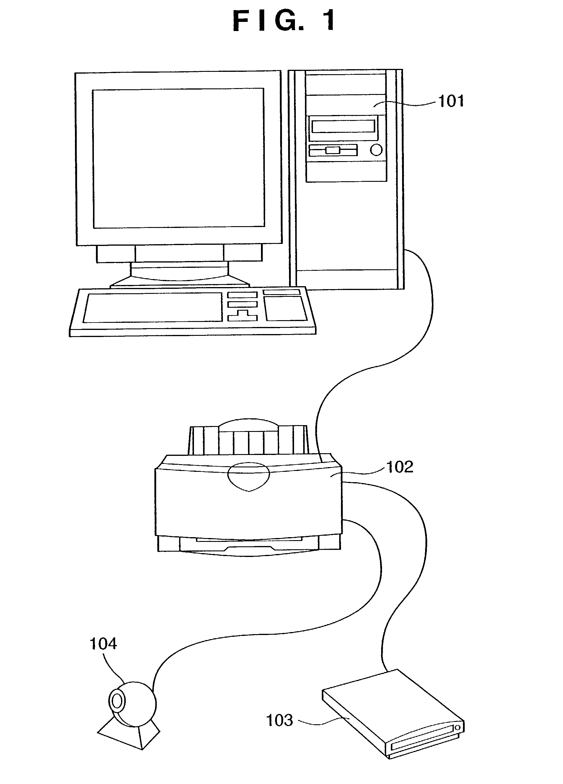
[0051]FIG. 1 shows a general connection configuration of a system to which the present invention is applied. In FIG. 1, an ink-jet printer 102 as a print device, a storage device 103 used to save data, and a communication camera 104 as a device for always capturing an image are connected to a personal computer 101 via a serial interface.

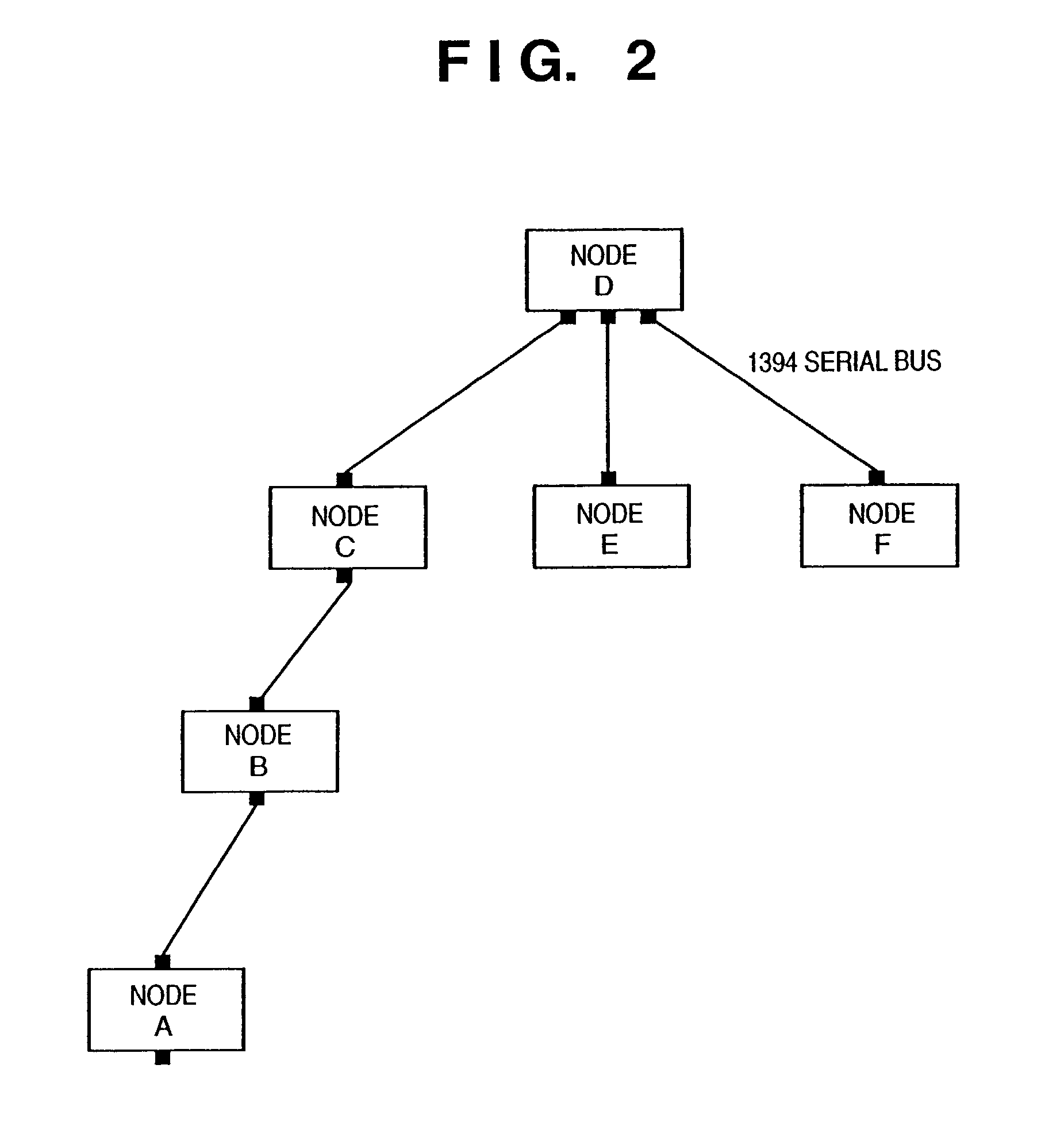
[0052]In the system of this embodiment, since the serial interface that connects respective devices uses an IEEE1394 interface, an outline of the IEEE1394-1995 standard technology will be explained first. Note that details of the IEEE1394-1995 standard (to be referred to as the IEEE1394 standard hereinafter) are described in “IEEE Standard for a High Performance Serial Bus” published by IEEE (The Institute of Electrical and Electronics Engineers, Inc.) on Aug. 30, 1996.

[0053]

[0054...

second embodiment

[0220]In the first embodiment, consumption power can be perfectly cut by turning off the power supply circuit of the device by the power saving control. However, in order to resume the device, a power supply startup sequence starting from a power ON operation must be executed, resulting in a long startup time. That is, no problem is posed if a response to the LINK_ON packet sent on the serial bus can be sent back within an allowable time of a partner device. However, some device may start an error process when it cannot wait that response. If the response time is preferentially shortened, since a measure is taken using the sleep mode as the power saving control, consumption power increases in such case even in a standby state as long as ICs that make clock operations are present.

[0221]In the second embodiment, a suspend state (suspend mode) 3003 is added as power saving control, as shown in the status transition chart of FIG. 30. In the suspend mode 3003, all clocks to be supplied t...

third embodiment

[0224]As described above, the three states, i.e., the sleep, suspend, and shutdown modes as power saving modes have been individually explained. One device can selectively use these three power saving modes.

[0225]FIGS. 31 and 32 show a state wherein one device makes the transition to a power saving mode.

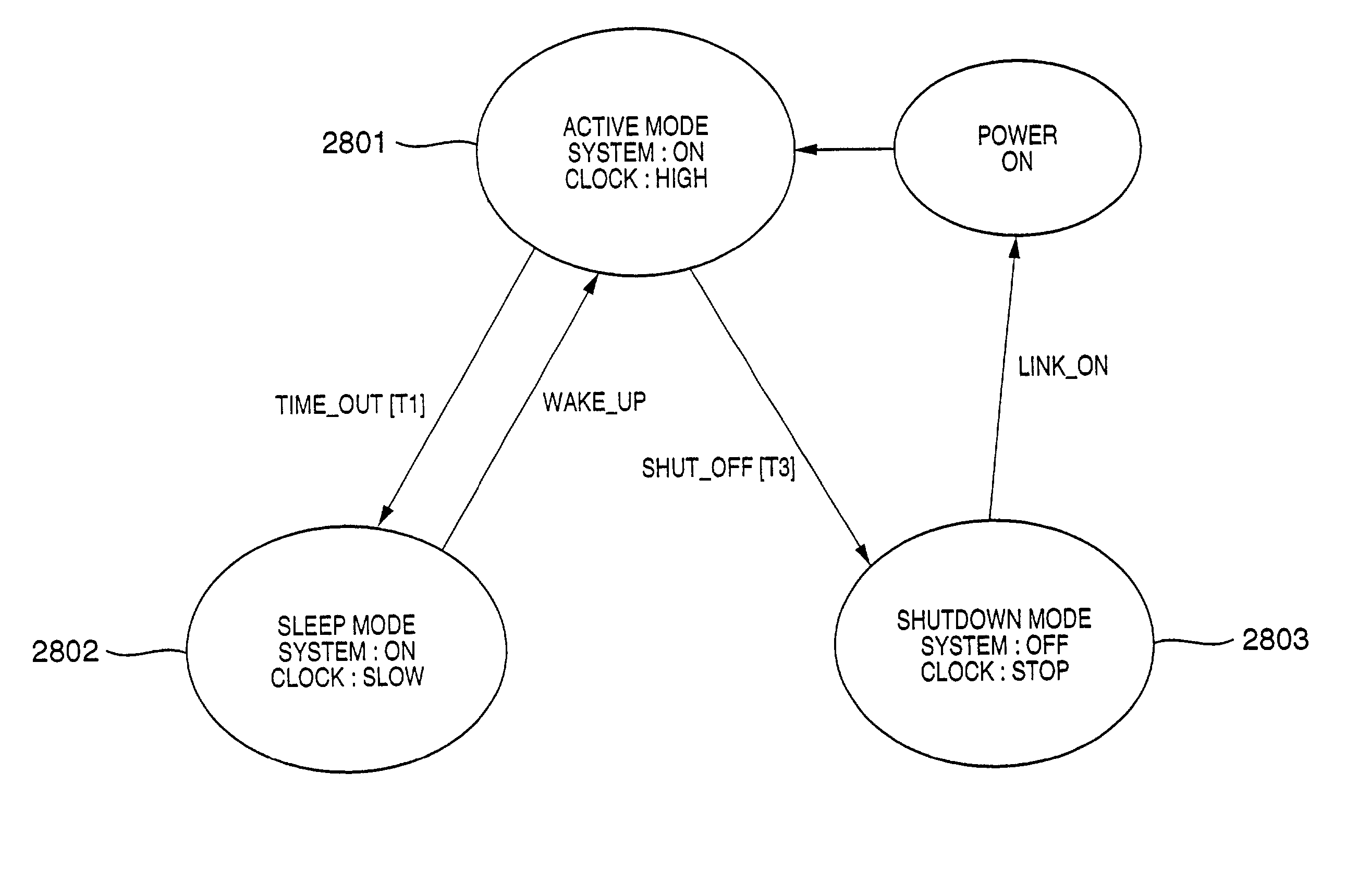
[0226]A TIME_OUT signal is generated after an elapse of a predetermined wait time from an active mode 3101 in which a normal operation is made, thus setting a sleep mode 3102. In this state, since a CPU operates slowly, it consumes electric power to some extent. After an elapse of a wait time T2, the device temporarily transits to the active mode 3101 to prepare for transition to a suspend mode 3103. The device then transits to the suspend mode 3103, in which clocks are halted, in response to a SUSPEND signal. Furthermore, after an elapse of a wait time T3, a power supply circuit is turned off in response to a SHUT_OFF signal, thus setting a shutdown mode 3104. The contents of the tr...


PUM


Abstract

A device of this invention solely executes a power saving operation without influencing a repeater operation on a serial bus interface to which a plurality of devices are cascade-connected.
A device such as a digital camera, printer, or the like, which is cascade-connected using an IEEE1394 serial bus interface, uses an IC prepared by forming both physical and link layers on a single chip. This IC has a port connected to a bus. When a power supply on the bus side is OFF, this port can insulate the bus in DC term. This device transits to a power saving mode such as a sleep mode, suspend mode, shutdown mode, or the like after an elapse of a predetermined wait time. In the shutdown mode, the system power supply of the device is turned off, but the IC can operate by electric power supplied from a cable. With this operation, a signal can be relayed between devices, and a packet for the link layer can be received. Upon receiving a LINK_ON packet, the device is restored from the power saving mode to a normal drive state.

Description

FIELD OF THE INVENTION[0001]This invention relates to a power saving control technique which can reduce the consumption power of a device without influencing another connected device upon exchanging data between devices, which are connected to each other via a communication line, especially, a high-speed serial bus (e.g., a serial interface specified by IEEE1394) that allows cascade connection.BACKGROUND OF THE INVENTION[0002]Conventionally, upon printing image data sensed by a digital camera using a printer, a method of connecting a personal computer and digital camera using a serial interface such as RS-232C or the like to download image data to the personal computer, a method of directly loading image data to the personal computer using a memory card incorporated in the digital camera, or the like is used. Image data fetched by the personal computer is transferred to a printer, which is connected to that personal computer via a parallel interface such as a Centronics interface or...

Claims


Application Information

Patent Timeline
IPC IPC(8): G06F1/00G06F1/32B41F1/00G06F1/04G06F13/42G06F15/00H04L12/12
CPCG06F13/4291H04L12/12Y02B60/34Y02B60/1235Y02B60/32Y02B60/1228Y02D10/00Y02D30/50
Inventor TATEYAMA, JIRO
Owner CANON KK
Why Eureka
Try Eureka