Decontamination of process streams

a technology of process stream and filter element, which is applied in the direction of separation process, physical/chemical process catalyst, filtration separation, etc., can solve the problems of contaminated backwash stream, high cost of filtration element and effort to change out or clean these guard filters, and low filtration capacity of fixed filter units. achieve the effect of improving filtration of contaminants

Active Publication Date: 2008-07-01
CRYSTAPHASE PRODS
View PDF74 Cites 19 Cited by
  • Summary
  • Abstract
  • Description
  • Claims
  • Application Information

AI Technical Summary

Benefits of technology

[0018]In accordance with the invention, the present invention advantageously provides a method of removing contaminants from a process stream. The method of removing contaminants preferably includes providing a plurality of reticulated elements in a vessel. The vessel is preferably located upstream of a process unit in which a decontaminated process stream can be processed, stored, transported, or the like. The vessel can be a separate vessel or a segment of pipe. The vessel can also be referred to as a guard filter. The vessel is preferably randomly packed with the plurality of reticulated elements within the vessel so that the plurality of reticulated elements provides enhanced filtration of contaminants within a process stream on a surface of the plurality of reticulated elements. The vessel may also contain quantities of other materials including conventional filter media, support balls, distributors and the like. The contaminated process stream contacts the plurality of reticulated elements, which removes contaminants from the contaminated process stream while allowing the contaminated process stream to pass unimpeded through the plurality of reticulated elements thereby producing a substantially decontaminated process stream. The substantially decontaminated process stream can be sent to a process unit for further processing, storage, transport or the like.
[0022]An additional feature of the present invention can include the step of using reticulated foam elements in a variety of porosities and pore sizes. The reticulated foam elements can be manufactured such that they have a porosity of so many pores per inch (“ppi”). Pore size in this context is the general size of the cavity of the pore recognizing that pores are not perfect spheres. Another important element of pore size is the size of the window opening into the pore. It is this measure that determines the size of the largest particle that can be trapped or filtered within the pore. The porosity range of the reticulated foam elements of the present invention are from 4 to 800 ppi. This enables customization of the size and shape of the reticulated foam elements for the application constraints including particulate loading and pressure drop constraints. The pores of the reticulated foam elements can be in a range of about 6 millimeters to about 100 microns, each being defined by a plurality of web members forming a plurality of flow passageways through the reticulated foam elements.

Problems solved by technology

While high filtration efficiencies can be achieved, the filtration capacity of these fixed filter units is relatively small, which typically requires changing out filter elements or backwashing or otherwise cleaning the filters on a regular and frequent basis.
The cost of filtration elements and the cost of the effort to change out or clean these guard filters can be expensive.
Sometimes the process stream itself is used to backwash the filtration system, which results in the backwash stream becoming contaminated with particulates and often downgraded in value.
It is estimated, for example, that some petroleum refineries incur a downgrade cost of over one million dollars per year to operate a fixed feed filter system on a 40,000 barrel per day hydroprocessing unit.
Additionally, if only one fixed feed filter system is used, there is a significant time period during cleaning, backwashing, or filter element replacement when unfiltered feed is fed to the downstream process unit.
These periods of unfiltered feed can contribute to pre-mature performance problems in the process unit, which results in more frequent downtime and higher maintenance costs.
Shortcomings of conventional guard filters include clogging of the filter medium, the limited capacity of the filter medium to remove particulates, the inability of deep bed filter media to trap particles less than about 25 microns in size, and inability of many fixed filter media to withstand elevated temperatures when required.
In conventional guard filters, the filter medium eventually clogs or blocks flow through the filter medium.
When the filter medium clogs, the flow rate of the stream through the filter medium drops and the pressure drop across the guard filter rises eventually to unacceptable levels at which point the guard filter must be taken off-line for filter media replacement or cleaning.
Conventional filter media have limited capacity to remove particulates.
It is this layer that clogs first as the particulates fill the void spaces through which the process stream is trying to flow.
This produces an impenetrable cake of particulates and causes the filter system pressure drop to eventually rise to unacceptable levels.
Contaminants in process streams can be deleterious to processes and also to process units.
Contaminants can damage process units, potentially resulting in an environmental or safety incident.
Contaminants can also damage processes by decreasing efficiencies within processes, deactivating or poisoning catalysts, reducing the yield of desired products, reducing the conversion rates of desired components, increasing the rate of generation of undesired products, stopping production, affecting the specifications of products, or the like.
Disadvantages associated with current perpendicular flow distribution designs and methods in deep bed filter units can result in poor distribution within the guard filter.
Clogging or other fouling, such as that caused by particulate contaminants or the products of undesired polymerization reactions, may also cause maldistribution.
The maldistribution may result in channeling and corresponding bypassing of portions of the filter media, reduction in the efficiency of contaminant removal, and reduction in efficiency of the guard filter.

Method used


Image

  • Decontamination of process streams
  • Decontamination of process streams
  • Decontamination of process streams

Examples


example 1

Use of Reticulated Elements in a Feed Filter

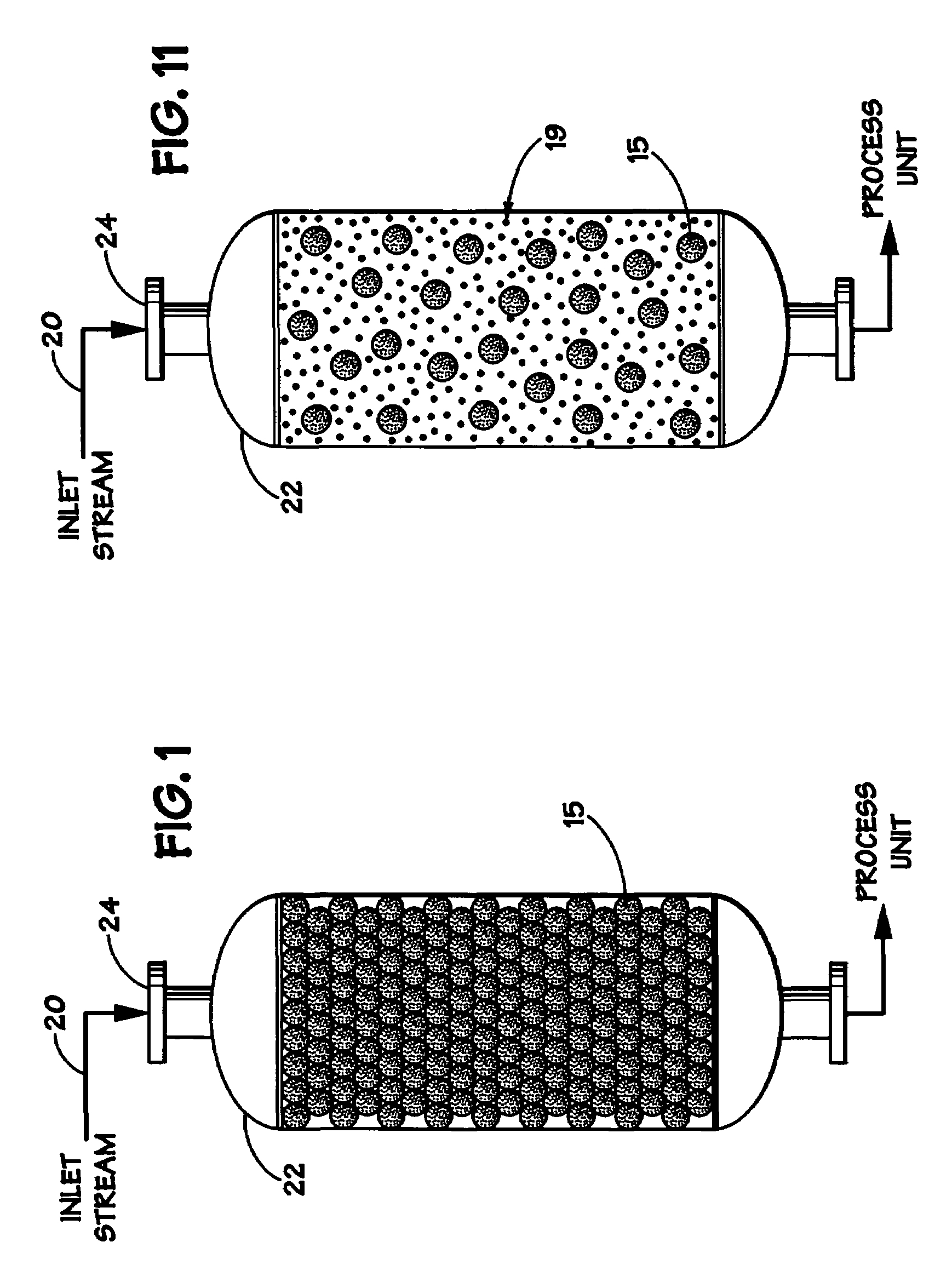
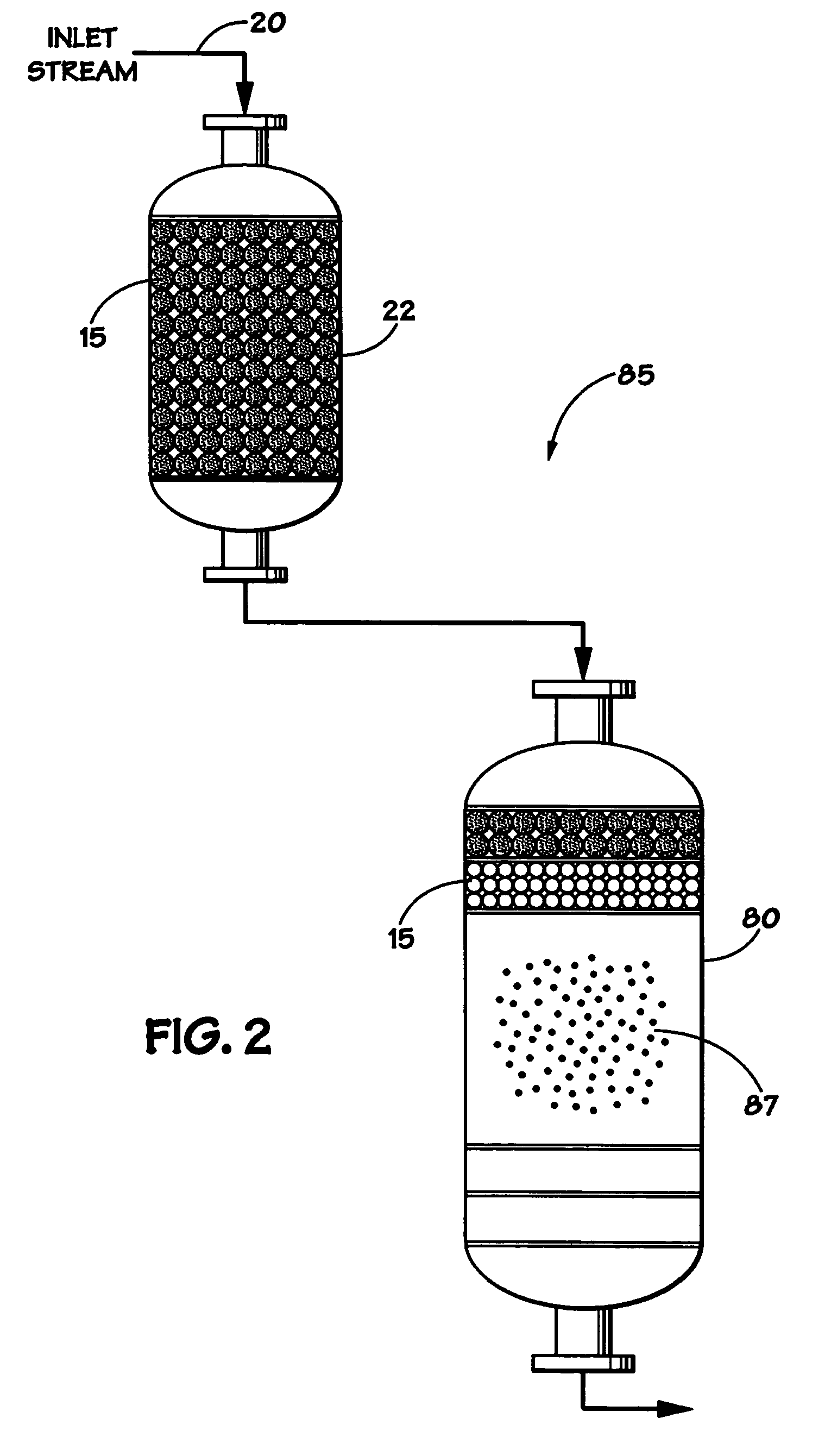
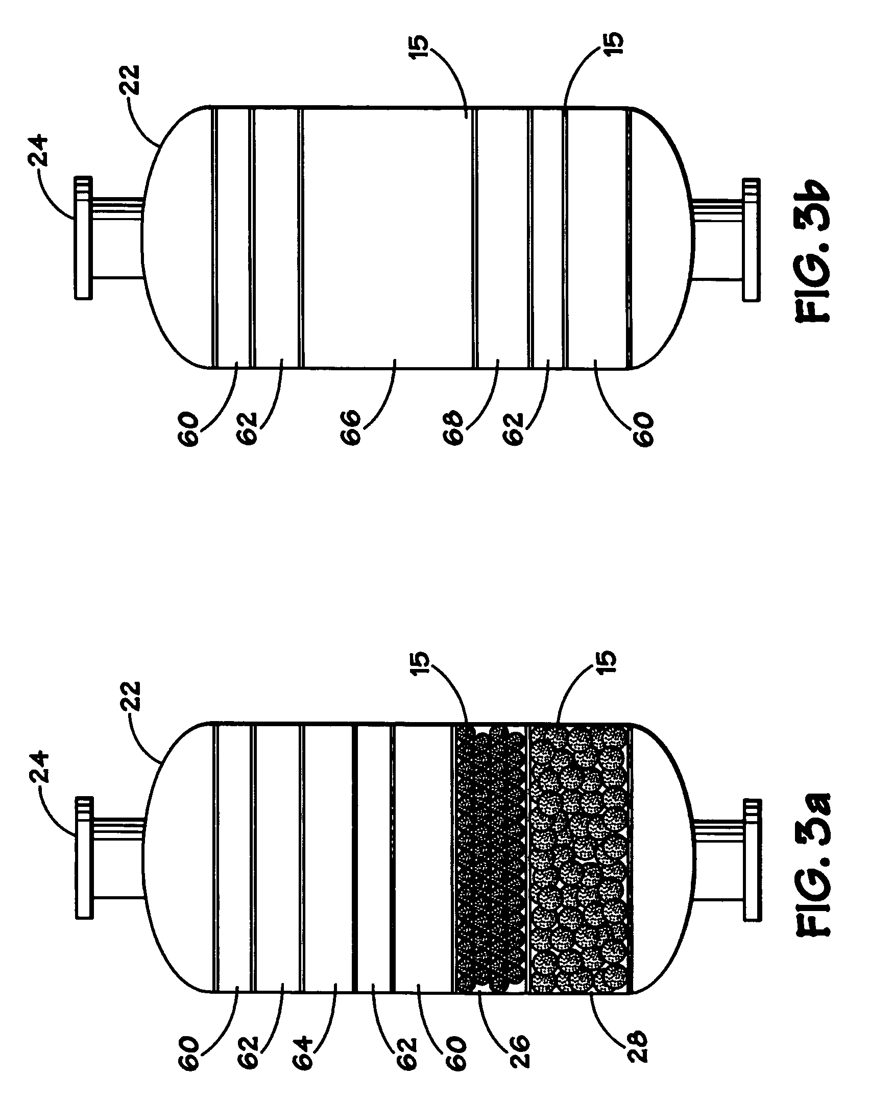
[0056]The use of reticulated elements 15 in a pre-filter vessel 22 in accordance with an embodiment of the present invention was compared with the use of conventional filter media in the pre-filter vessel 22. The reticulated elements 15 of the present invention were installed in a pre-filter vessel 22, as shown in FIG. 3a. Two layers of reticulated elements 26, 28 were installed in the vessel 22. Each layer 26, 28 of reticulated element had a different porosity. Along with the reticulated elements 15, conventional support media, including ⅜″ inert balls 60, ¼″ inert balls 62, and 1.6 mm diameter spent catalyst 64, was also installed in the vessel 22.

[0057]When the prior art filter media was installed in a pre-filter vessel 22, as shown in FIG. 3b, ⅜″ inert balls 60, ¼″ inert balls 62, and spent catalysts 66, 68 were installed in the vessel 22. When in operation with the prior art filter media installed, the pre-filter vessel 22 could only ...


PUM

PropertyMeasurementUnit
sizeaaaaaaaaaa
sizeaaaaaaaaaa
sizeaaaaaaaaaa

Abstract

A method for removing contaminants from a process stream that includes the use of reticulated material to filter the process stream in a vessel located upstream of a process unit. The reticulated material can be used with other conventional filter media within the vessel.

Description

RELATED APPLICATION [0001]This application is a continuation-in-part of U.S. patent application Ser. No. 10 / 396,851, filed on Mar. 25, 2003 now U.S. Pat. No. 7,265,189.BACKGROUND OF THE INVENTION[0002]1. Field of the Invention[0003]The invention relates to a method of providing filtration of contaminants from process streams. More specifically, the invention relates to a method of providing filtration of contaminants from process streams upstream of process units.[0004]2. Description of Related Art[0005]Refineries, petrochemical plants and other similar type plants process large amounts of both liquids and / or vapor phase process streams through a variety of process units. Feed filters and other pre-filter systems, which are also referred to as guard beds or guard filters, are frequently used to remove undesired particulates from the process streams prior to being fed to a process unit. As used herein, these feed filters and pre-filter systems will be referred to as guard filters. Gu...

Claims


Application Information

Patent Timeline
Patent Type & Authority Patents(United States)
IPC IPC(8): B01J8/12B01J8/18B01D3/14B01D3/16B01D39/06B01D46/00B01D53/04B01D53/86B01J8/04B01J8/26B01J19/30B01J23/85C08F2/00
CPCB01J8/0469B01J8/0453B01J19/30B01D39/06B01D53/02B01D53/86B01J8/26B01J23/85B01J2219/30203B01J2219/30207B01J2219/30223B01J2219/30226B01J2219/30246B01J2219/30408B01J2219/30416B01J2219/30425B01J2219/30475B01J2219/3083B01J2219/32296B01D3/14B01D3/16B01D2253/308B01D2253/311B01D2253/342B01D2257/30B01D2258/0291B01D2275/10B01D2275/30
Inventor GLOVER, JOHN N.DUKE, WILLIAM D.HAM, PETER G.
Owner CRYSTAPHASE PRODS
Why Eureka
Try Eureka