Dispensing device, dispensing method and method of detecting defective discharge of solution containing biological sample

a technology of dispensing device and biological sample, which is applied in the field of dispensing technology for spotting biological sample, can solve the problems of poor production efficiency, difficult to realize stable discharge characteristics, and difficulty in preparing high-quality protein chips, and achieve the effect of high quality

Inactive Publication Date: 2008-07-08
SEIKO EPSON CORP
View PDF20 Cites 15 Cited by
  • Summary
  • Abstract
  • Description
  • Claims
  • Application Information

AI Technical Summary

Benefits of technology

[0006]Accordingly, an object of the present invention is to propose dispensing technology enabling the reliable spotting of a biological sample on a solid phase. Another object of the present invention is to realize a faster preparation of microchips.
[0046]According to the foregoing method, cross contamination is suppressed as much as possible, and a high quality microarray can be prepared thereby.

Problems solved by technology

Nevertheless, generally speaking, a protein solution is highly viscous, and, since such viscosity varies depending on the type of protein, it is difficult to realize stable discharge characteristics upon performing spotting on a solid phase with an inkjet head.
In particular, when the trajectory of the protein solution becomes unstable, cross contamination will occur, and it is therefore difficult to prepare a high quality protein chip.
Further, with conventional methods, there are problems in that much time is required for preparing a protein chip formed of a large variety of proteins, the production efficiency is thereby inferior, proteins would become deactive with the lapse in time, and the reliability of the protein chip would deteriorate as a result thereof.
Similar problems also arise upon preparing a DNA microarray.

Method used


Image

  • Dispensing device, dispensing method and method of detecting defective discharge of solution containing biological sample
  • Dispensing device, dispensing method and method of detecting defective discharge of solution containing biological sample
  • Dispensing device, dispensing method and method of detecting defective discharge of solution containing biological sample

Examples


embodiment 1

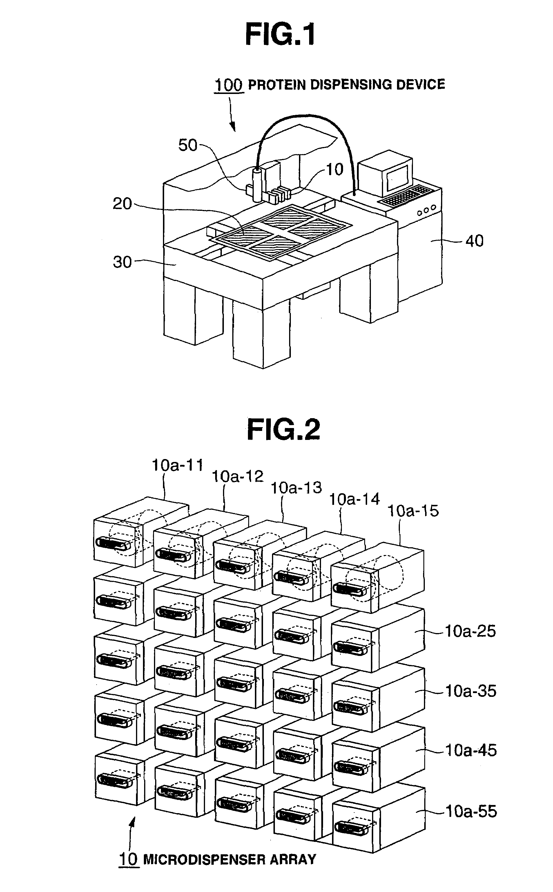
[0061]FIG. 1 is a structural diagram of the protein dispensing device in the present embodiment.

[0062]This device 100 is structured by having a microdispenser array 10 for approximately simultaneously discharging foreign protein, a protein chip 20 in which a large variety of proteins has been spotted in a high density array shape, a stage 30 for mounting the protein chip 20, a drive control device 40 for relatively moving the microdispenser array 10 and protein chip 20 and performing discharge control of the protein solution, and a CCD sensor 50 for optically detecting the discharge status of the protein solution on the protein chip 20.

[0063]FIG. 2 is a structural diagram of the microdispenser array 10.

[0064]This array 10 has a structure in which microdispensers 10a-ij are arranged in a matrix shape at a position of i lines×j columns. In FIG. 2, exemplified is a structure of 5 lines and 5 columns. Each of the microdispensers 10a-ij is structured to mutually discharge different prote...

embodiment 2

[0096]In the present embodiment, as a method of discriminating the defective discharge of a nozzle, adopted is a method of optically detecting the droplet discharge. FIG. 12 is a structural diagram for optically detecting the droplet discharge, and illustrated therein are a head chip 12, a spotting substrate 21, a droplet 70 containing protein, a droplet trajectory 71, a laser light source 61, a light reception sensor 62, and a laser beam 63.

[0097]For example, in the control means Y structured by including a CPU, when a drive signal is supplied, the droplet 70 is discharged from the head chip 12 toward the substrate 21. If an optical detection means structured from the laser light source 61 and light reception sensor 62 is disposed at the position in which the droplet trajectory 71 and the laser beam 63 intersect, the detection level of the light reception sensor 62 will change when the droplet 70 intersects with the laser beam 63, and the discharge of the droplet 70 may thereby be ...


PUM

PropertyMeasurementUnit
surface tensionaaaaaaaaaa
thicknessaaaaaaaaaa
distanceaaaaaaaaaa

Abstract

Proposed is dispensing technology capable of reliably spotting a biological sample on a solid phase. A head chip applies a voltage pulse between a diaphragm and separate electrodes based on a drive control signal output from a head driver IC, and discharges a solution containing protein filled in a pressurized chamber as a result of the elastic deformation of the diaphragm. A drive pulse generation circuit generates a drive voltage pulse and supplies this to the head chip in order to discharge a solution containing protein from the head chip. The drive current detection circuit detects a drive current flowing between the diaphragm and separate electrodes. Since the waveform of the detected drive current and the peak current value and so on differ in the case where the discharge status is normal and in the case where it is abnormal, a defective discharge can be discriminated by detecting such change.

Description

BACKGROUND OF THE INVENTION[0001]1. Field of the Invention[0002]The present invention generally relates to dispensing technology for spotting a biological sample such as protein or nucleic acid on a solid phase, and particularly to improved technology suitable in preparing a microchip.[0003]2. Description of the Related Art[0004]Pursuant to the advancement in biotechnology, human genome has been decoded, and genetic research is making a transition to the stage of structural analysis and functional analysis of protein. For instance, in the research of medicine or the like, research concerning proteomics; that is, how proteins relate to medical conditions as well as the development of chemicals capable of suppressing the working of such proteins, is becoming increasingly important. In this type of proteomics research, employed is a protein chip in which various proteins are spotted on a substrate. As a preparation method of such a chip, for example, as disclosed in Japanese Patent Lai...

Claims


Application Information

Patent Timeline
Patent Type & Authority Patents(United States)
IPC IPC(8): B41J29/38B01L3/00B41J2/045G01N33/53G01N27/447G01N35/10G01N37/00
CPCG01N35/1074Y10T436/2575G01N2035/1041G01N2035/1018
Inventor FUJII, MASAHIROKOEDA, HIROSHITAKAGI, FUMIO
Owner SEIKO EPSON CORP
Why Eureka
Try Eureka