
Image forming method and image forming apparatus

a technology of image forming and forming method, which is applied in the direction of electrographic process apparatus, instruments, corona discharge, etc., can solve the problems of affecting the image quality, and difficulty in reproducing halftones, etc., and achieves high contrast, high image quality, and high gradation.

Active Publication Date: 2008-07-08
CANON KK
View PDF11 Cites 51 Cited by
  • Summary
  • Abstract
  • Description
  • Claims
  • Application Information

AI Technical Summary

Benefits of technology

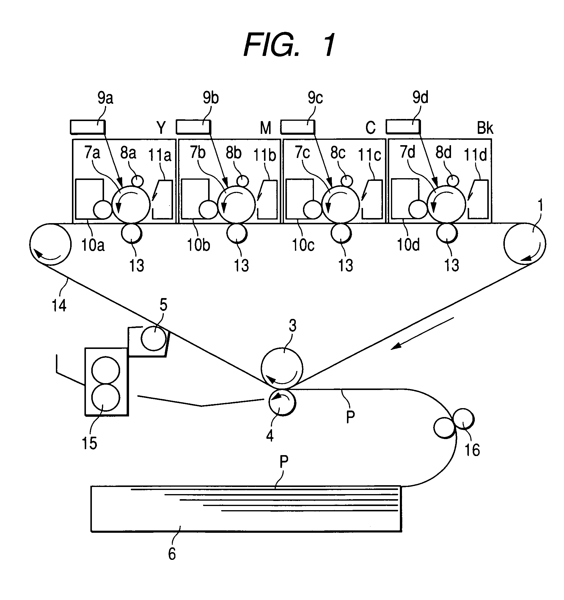
The present invention provides an image forming method and apparatus that can solve problems such as low image quality, carrier adhesion, and unstable image formation over time. The invention achieves high gradation and halftone reproduction, prevents fine scratches and wear on the photosensitive member surface, and holds toner in a large quantity on the carrier. The invention also uses a two-component developer with a specific toner and a charge transport layer, and a carrier with a specific hardness and modulus of elastic deformation. Additionally, the invention uses a photosensitive member with a divided charge transport layer and a specific curable resin. The invention achieves stable image formation over a long period of time and prevents abrasion and fine scratches on the photosensitive member surface.

Problems solved by technology

However, in full-color copying machines or printers, which are required to provide high image quality for halftone, problems may arise such that it is difficult to reproduce the halftone because the γ curve has a sharp slant in the halftone region, and that image density varies greatly because of a slight variation in potential to make it difficult to reproduce colors.
However, in the case when the thin-film photosensitive member as stated above is used, which has a high resolution but has a sharp slant in the γ curve, it is necessary for the toner to have a very large charge quantity in order to make the gradation high, and developing performance, i.e., what is called “toner release” from carrier, is not sufficiently satisfied in some cases.
Also, if the toner has a large charge quantity, counter charges are liable to be collected in the carrier to cause carrier adhesion.
On such an occasion, if the carrier has an amorphous particle shape, the photosensitive drum tends to be finely scratched at its surface even when it has a tough protective layer, so that the surface of the photosensitive drum may become matte with progress of running to cause coarse images or lines at halftone areas.

Method used


Image

  • Image forming method and image forming apparatus
  • Image forming method and image forming apparatus
  • Image forming method and image forming apparatus

Examples


examples

[0238]The present invention is described below in greater detail by giving specific working examples. The present invention is by no means limited to these examples.

Carrier Production Example A

[0239]To each of fine magnetite particles having a number-average particle diameter of 250 nm and a resistivity of 5.1×10⁵ Ω·cm (intensity of magnetization under 79.6 kA / m: 64 Am2 / kg; true specific gravity: 5.2 g / cm3) and fine hematite particles having a number-average particle diameter of 260 nm and a resistivity of 4.9×10⁷ Ω·cm (non-magnetic; true specific gravity: 5.1 g / cm3), 4.0% by weight of a silane coupling agent 3-(2-aminoethylaminopropyl)trimethoxysilane was added, and these were high-speed mixed and agitated at 110° C. in a container to carry out surface treatment.

[0240]

(by weight)Phenol10 partsFormaldehyde solution 6 parts(aqueous 37% by weight formaldehyde solution)Above treated fine magnetite particles76 partsAbove treated fine hematite particles 8 parts

[0241]The above materials, ...

production example b

Carrier Production Example B

[0245]To each of fine magnetite particles having a number-average particle diameter of 250 nm and a resistivity of 5.1×10⁵ Ω·cm (intensity of magnetization under 79.6 kA / m: 64 μm2 / kg; true specific gravity: 5.2 g / cm3) and fine hematite particles having a number-average particle diameter of 610 nm and a resistivity of 1.3×10⁸ Ω·cm (non-magnetic; true specific gravity: 5.3 g / cm3), 0.8% by weight of a silane coupling agent 3-(2-aminoethylaminopropyl)trimethoxysilane was added, and these were high-speed mixed and agitated at 110° C. in a container to carry out surface treatment.

[0246]

(by weight)Phenol10 partsFormaldehyde solution 6 parts(aqueous 37% by weight formaldehyde solution)Above treated fine magnetite particles60 partsAbove treated fine hematite particles24 parts

[0247]The above materials, and 5 parts by weight of 28% by weight ammonia water and 10 parts by weight of water were put into a flask, and were thoroughly mixed. At this point, the dissolved o...

production example c

Carrier Production Example C

[0249]To each of fine magnetite particles having a number-average particle diameter of 250 nm and a resistivity of 5.1×10⁵ Ω·cm (intensity of magnetization under 79.6 kA / m: 65 μm2 / kg; true specific gravity: 5.2 g / cm3) and fine hematite particles having a number-average particle diameter of 260 nm and a resistivity of 4.9×10⁷ Ω·cm (non-magnetic; true specific gravity: 5.1 g / cm3), 3.0% by weight of a titanium type silane coupling agent isorpopyltri(N-aminoethyl-aminoethyl)titanate was added, and these were high-speed mixed and agitated at 110EC in a container to carry out surface treatment.

[0250]

(by weight)Phenol10 partsFormaldehyde solution 6 parts(aqueous 37% by weight formaldehyde solution)Above treated fine magnetite particles76 partsAbove treated fine hematite particles 8 parts

[0251]The above materials, and 6 parts by weight of 28% by weight ammonia water and 8 parts by weight of water were put into a flask, and were thoroughly mixed. At this point, th...


PUM


Abstract

An image forming method and an image forming apparatus are disclosed in which an electrostatic latent image is formed on a photosensitive member surface by using a two-component developer including a toner and carrier. The photosensitive member surface has a specific modulus of elastic deformation and includes a charge transport layer with a specific thickness. The toner has a specific weight-average particle diameter. The carrier has a specific volume-average particle diameter and a specific circularity, and contains 20% by number or less of particles having a value of “average circularity−2σ” where σ is standard deviation of carrier circularity.

Description

BACKGROUND OF THE INVENTION[0001]1. Field of the Invention[0002]This invention relates to an image forming method and an image forming apparatus which make use of a two-component developer having a toner and a carrier, used in electrophotography or electrostatic recording and so forth, to develop an electrostatic latent image on a photosensitive member to form an image.[0003]2. Related Background Art[0004]In general, in image forming apparatus by which images are recorded on recording mediums such as paper, as in printers, an electrophotographic system is employed as a system by which the images are recorded on the recording mediums.[0005]The electrophotographic system employs as an electrostatic latent image bearing member a photosensitive drum coated with a photosensitive material on its surface. First, the surface of the photosensitive drum is uniformly electrostatically charged, and thereafter the surface of the photosensitive drum is exposed to laser light, so that a potential ...

Claims


Application Information

Patent Timeline
Patent Type & Authority Patents(United States)
IPC IPC(8): G03G15/08G03G15/09
CPCG03G15/09G03G2215/00957
Inventor BABA, YOSHINOBUFUJIKAWA, HIROYUKISUGAHARA, NOBUYOSHIISHIGAMI, KOHOKAMOTO, NAOKIITAKURA, TAKAYUKI
Owner CANON KK
Learn More