Aeroengine intake having a heat exchanger within an annular closed chamber

a technology of heat exchanger and aeroengine, which is applied in the direction of machines/engines, efficient propulsion technologies, transportation and packaging, etc., can solve the problems of loss of performance and engine malfunction, ice breaking away, and the edge of the intake of aeroengines is particularly prone to icing, so as to prevent ice formation

Inactive Publication Date: 2008-07-15
ROLLS ROYCE PLC
View PDF10 Cites 70 Cited by
  • Summary
  • Abstract
  • Description
  • Claims
  • Application Information

AI Technical Summary

Benefits of technology

[0010]In accordance with the present invention a gas turbine engine is provided that comprises a nacelle having an intake, the intake defining a generally annular chamber, an engine accessory and a heat exchanger for cooling a fluid of the accessory characterised in that the chamber is closed and the heat exchanger is disposed within the chamber operable to provide heat to prevent ice forming on the intake during engine operation.
[0017]Preferably, the at least one rib increases in extent into the chamber generally from the heat exchanger thereby increasing its surface area for heat exchanging to provide a more constant heat exchange around the circumference of the intake.
[0018]Alternatively, further ribs are provided around the circumference to increase the surface area for heat exchanging around the intake to provide a more constant heat exchange around the circumference of the intake.
[0019]Preferably, the ribs also provide increased rigidity of the intake to protect against foreign body impacts.

Problems solved by technology

The leading edge of the intake of aeroengines is particularly prone to icing during flight through clouds containing super-cooled water droplets or ground operation in freezing fog.
Protection against ice formation may be required since icing of the intake may significantly affect the airflow through the engine, causing a loss of performance and possible malfunction of the engine.
In addition, damage may result from ice breaking away and being ingested into the engine or impacting acoustic liners around the intake duct.
Such a system inefficient as it requires additional electrical generation.
These systems are disadvantaged in that they use air bled from the compressor thereby reducing engine efficiency.
As this system employs engine oil, failure of the system is likely to compromise engine operability.
A further problem is that the heat sink and piping imposes a significant weight penalty to the engine and nacelle assembly.
However, a serious disadvantage with this arrangement is that the air scoop causes additional aerodynamic drag, therefore reducing the overall efficiency of the engine.

Method used


Image

  • Aeroengine intake having a heat exchanger within an annular closed chamber
  • Aeroengine intake having a heat exchanger within an annular closed chamber
  • Aeroengine intake having a heat exchanger within an annular closed chamber

Examples


Embodiment Construction

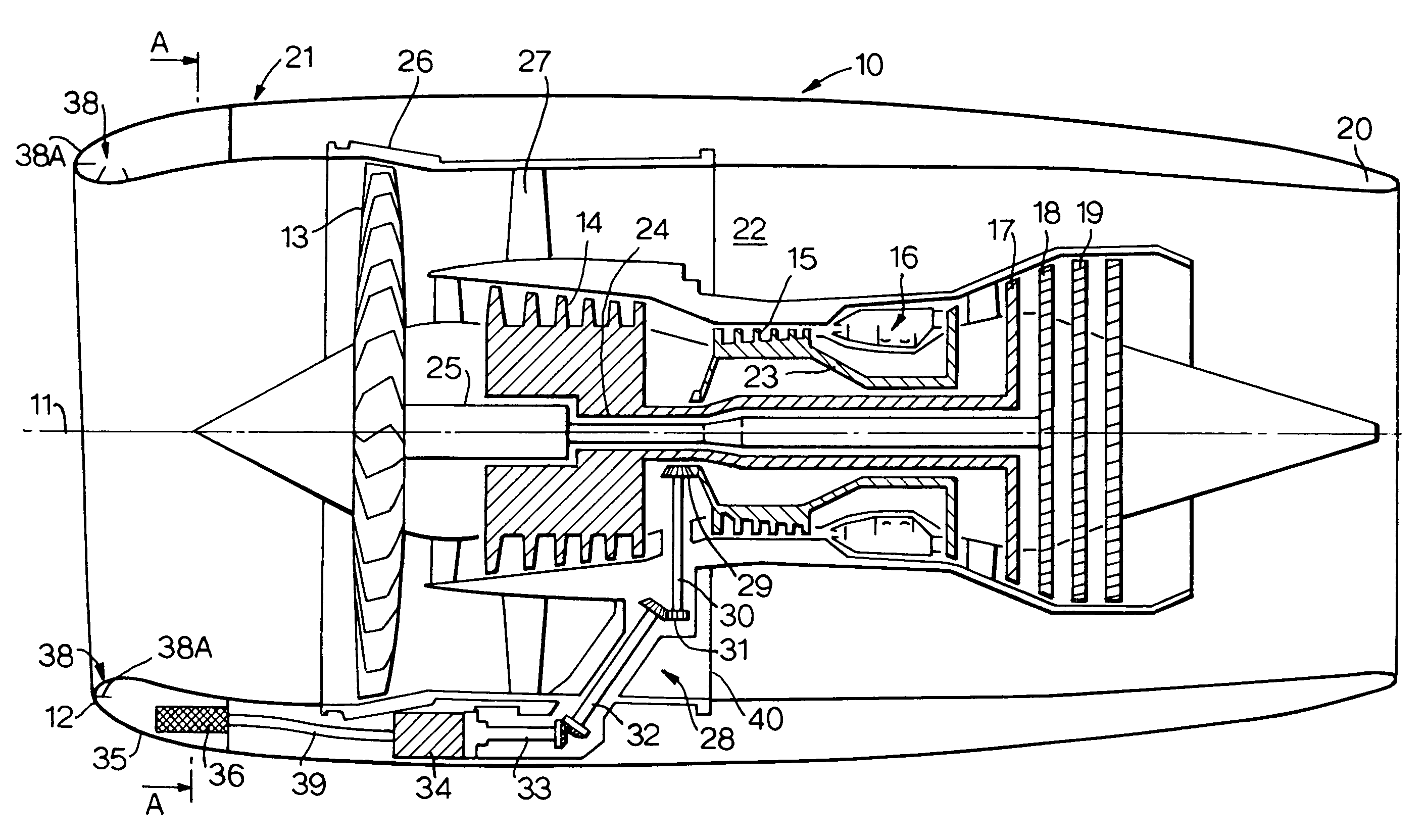
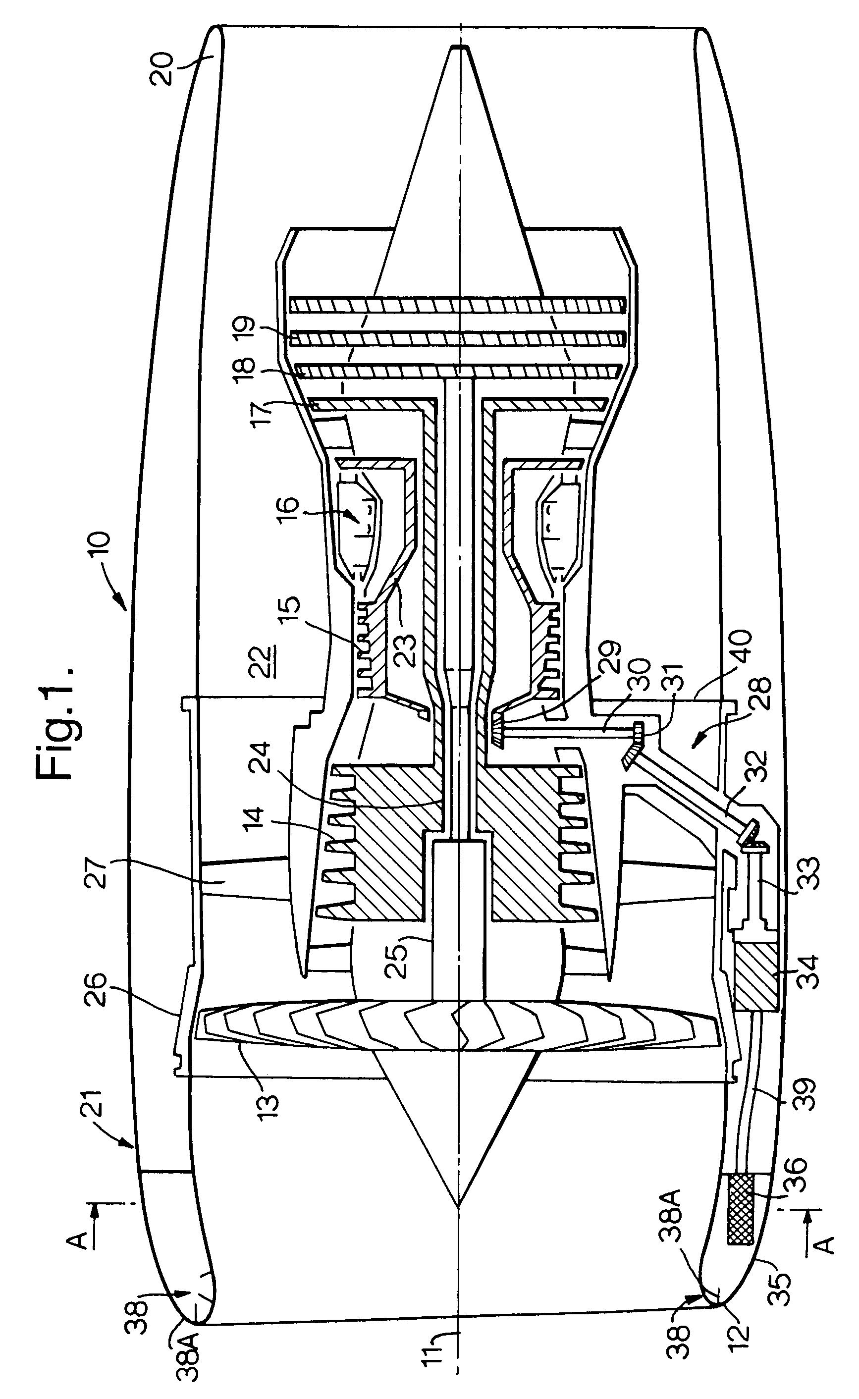
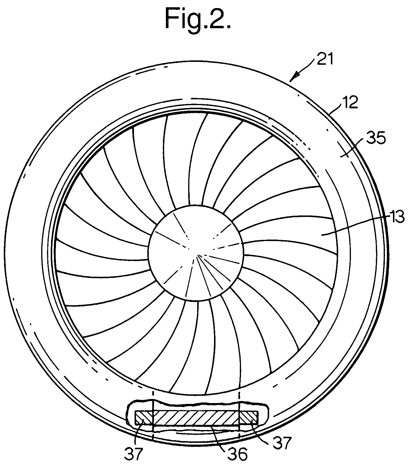
[0026]With reference to FIGS. 1 and 2, a ducted fan gas turbine engine generally indicated at 10 has a principal and rotational axis 11. The engine 10 comprises, in axial flow series, an air intake 12, a propulsive fan 13, an intermediate pressure compressor 14, a high-pressure compressor 15, combustion equipment 16, a high-pressure turbine 17, and intermediate pressure turbine 18, a low-pressure turbine 19 and an exhaust nozzle 20. A nacelle 21 generally surrounds the engine 10 and defines both the intake 12 and the exhaust nozzle 20.

[0027]The gas turbine engine 10 works in the conventional manner so that air entering the intake 11 is accelerated by the fan 13 to produce two air flows: a first air flow into the intermediate pressure compressor 14 and a second air flow which passes through a bypass duct 22 to provide propulsive thrust. The intermediate pressure compressor 14 compresses the air flow directed into it before delivering that air to the high pressure compressor 15 where ...


PUM


Abstract

A gas turbine engine comprising a nacelle having an intake, the intake defining a generally annular chamber, an engine accessory and a heat exchanger for cooling a fluid of the accessory. The chamber is closed and the heat exchanger is disposed within the chamber operable to provide heat to prevent ice forming on the intake during engine operation.

Description

TITLE OF THE INVENTION[0001]1. Field of the Invention[0002]The present invention relates to an intake of an aeroengine nacelle and in particular to providing a heated intake for prevention of ice build up thereon.[0003]2. Background of the Invention[0004]The leading edge of the intake of aeroengines is particularly prone to icing during flight through clouds containing super-cooled water droplets or ground operation in freezing fog. Protection against ice formation may be required since icing of the intake may significantly affect the airflow through the engine, causing a loss of performance and possible malfunction of the engine. In addition, damage may result from ice breaking away and being ingested into the engine or impacting acoustic liners around the intake duct.[0005]It is well known to provide the intake with an electrical element heating system, ducting to supply the intake with heated core engine air or piping to supply hot engine oil around to the intake prevent ice buil...

Claims


Application Information

Patent Timeline
Patent Type & Authority Patents(United States)
IPC IPC(8): F02G3/00F02C7/047F02C7/12F02C7/32
CPCF02C7/047F02C7/12F02C7/32Y02T50/675Y02T50/671Y02T50/60
Inventor STRETTON, RICHARD GBEARDSLEY, PETER
Owner ROLLS ROYCE PLC
Why Eureka
Try Eureka