Controller for ultrafiltration blood circuit which prevents hypotension by monitoring osmotic pressure in blood

a blood circuit and ultrafiltration technology, applied in the direction of solvent extraction, other blood circulation devices, separation processes, etc., can solve the problems of abnormal decrease in blood pressure of patients, lack of fluid removal ability, hypovolemic shock, etc., and achieve the effect of robust and inexpensive measurement system

Inactive Publication Date: 2008-07-15
GAMBRO LUNDIA AB
View PDF36 Cites 17 Cited by
  • Summary
  • Abstract
  • Description
  • Claims
  • Application Information

AI Technical Summary

Benefits of technology

[0027]c) Uses robust and ine

Problems solved by technology

Dialysis patients require removal of excess water from their blood because they lack the ability to rid their bodies of fluid through the normal urinary function.
One of the potential risks to health associated with RRT is hypotension, which is abnormal decrease in the patient's blood pressure.
An abnormally high or uncontrolled ultrafiltration rate may result in hypovolemic shock, hypotension, or both.
If too much water is removed from the patient's blood, such as might occur if the ultrafiltration rate is too high or uncontrolled, the patient could suffer hypotension and/or go into hypovolemic shock.
Certain kinds of RRT machine failures may result in fluid gain rather than fluid loss.
Specifically, inverse ultrafiltration may result in unintended weight gain of a patient and is potentially hazardous.
Uncontrolled infusion of fluid by whatever mechanism into the patient could result in fluid overload, with the most serious acute complication being pulmonary edema.
However, refilling of the plasma is often not completed during a dialysis session.
The delay in refilling the plasma can lead to insufficient blood volume in a patient.
When patients are ultrafiltered at a faster rate, they begin to experience symptomatic hypotension.
However, these controllers do not alway

Method used


Image

  • Controller for ultrafiltration blood circuit which prevents hypotension by monitoring osmotic pressure in blood
  • Controller for ultrafiltration blood circuit which prevents hypotension by monitoring osmotic pressure in blood
  • Controller for ultrafiltration blood circuit which prevents hypotension by monitoring osmotic pressure in blood

Examples


Embodiment Construction

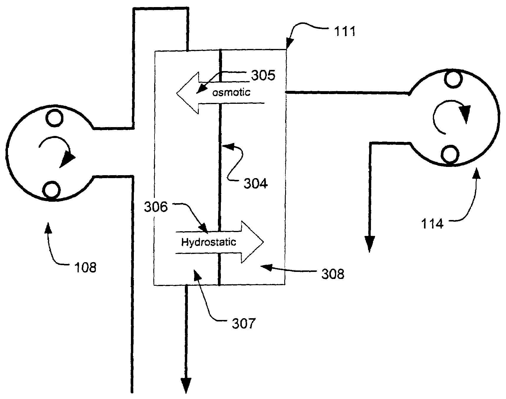
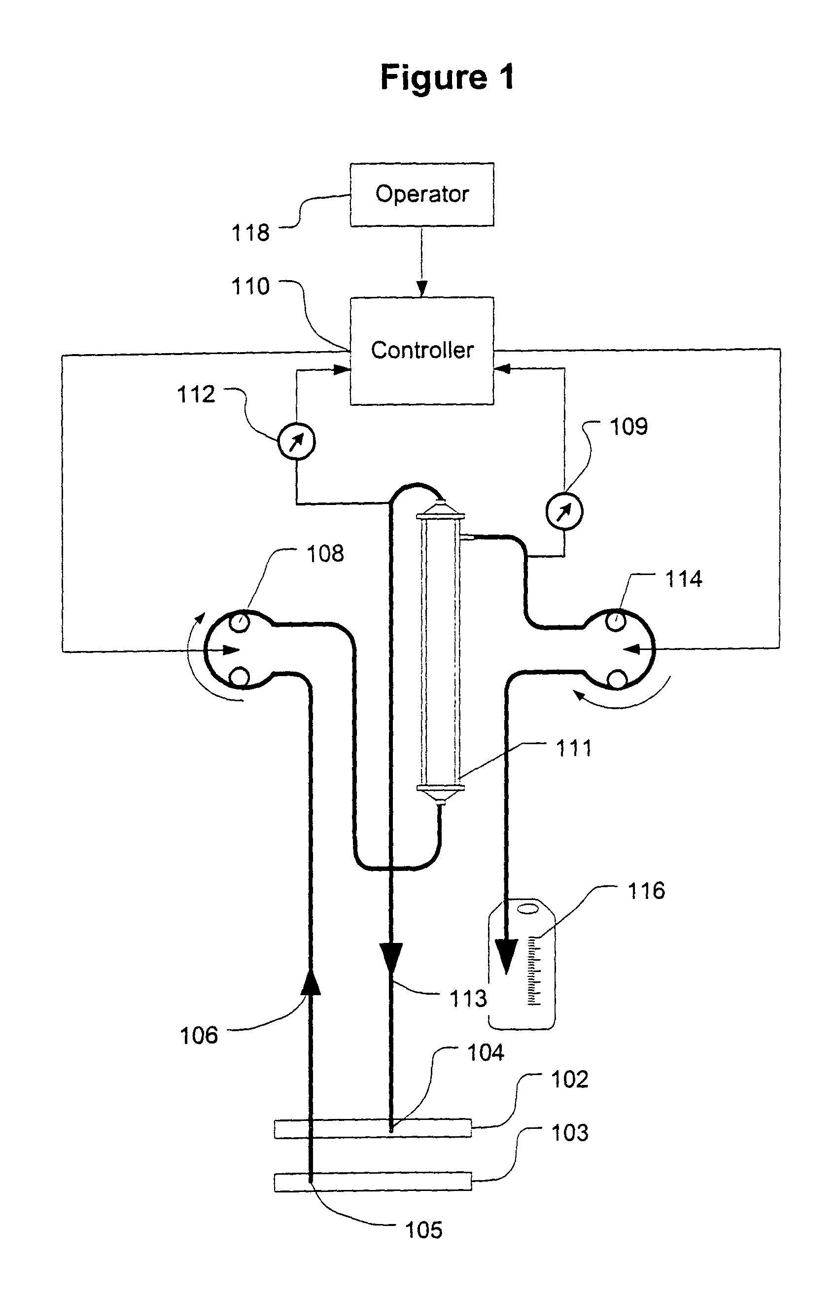
[0039]FIG. 1 shows a high level schematic diagram of an ultrafiltration system, such as is disclosed in commonly-owned U.S. Pat. No. 6,887,214 (U.S. patent application Ser. No. 09 / 660,195 filed Sep. 12, 2000), entitled “Blood Pump Having A Disposable Blood Passage Cartridge With Integrated Pressure Sensor”, and U.S. Pat. No. 6,585,675 (U.S. patent application Ser. No. 09 / 703,702 filed Sep. 12, 2000), entitled “Method And Apparatus For Blood Withdrawal And Infusion Using A Pressure Controller” and filed Nov. 2, 2000, both of which applications are incorporated by reference in their entirety.

[0040]Blood is withdrawn from the vein 103 of a human or other mammalian patient using a withdrawal needle 105. The blood flows from the needle into a withdrawal bloodline 106 that is equipped with an in-line pressure sensor 107. The sensor transmits a signal indicative of the blood pressure in the withdrawal line to a computer controller 110. The withdrawal line loops through a blood pump 108. Th...


PUM


Abstract

A method and system for the extracorporeal treatment of blood to remove fluid from the fluid overloaded patient is disclosed that non-invasively measures osmotic pressure across a filter membrane of a blood filter. The filter is permeable to water and electrolytes, but not to blood protein. The osmotic pressure indicates the protein concentration in the blood. Osmotic pressure is used to detect when hypotension is about to occur in a patient, as a result of excessive blood volume reduction during treatment of the blood. Using the osmotic pressure measurement as a feedback signal, the rate of fluid extraction is automatically controlled to achieve the desired clinical outcome and avoid precipitating a hypotensive crisis in the patient.

Description

[0001]This application is a continuation of and claims priority to application Ser. No. 09 / 721,778 filed Nov. 27, 2000 now U.S. Pat. No. 6,689,083. The present invention relates to an apparatus for the extracorporeal treatment of blood and more specifically to the automatic control fluid removal from the blood of patients suffering from fluid overload and averting therapy induced hypotension.FIELD OF INVENTIONBACKGROUND OF THE INVENTION[0002]Renal replacement therapy (RRT) has evolved from the long, slow hemodialysis treatment regime of the 1960's to a diverse set of therapy options, the vast majority of which employ high permeability membrane devices and ultrafiltration control systems.[0003]Biologic kidneys remove metabolic waste products, other toxins, and excess water. They also maintain electrolyte balance and produce several hormones for a human or other mammalian body. An artificial kidney, also called a hemodialyzer or dialyzer, and attendant equipment and supplies are desig...

Claims


Application Information

Patent Timeline
IPC IPC(8): A61M37/00C02F1/44A61M1/34A61M1/36
CPCA61M1/34A61M1/3609A61M1/367A61M1/3639A61M2230/20A61M2205/3331A61M2205/50A61M2205/3375A61M1/3403A61M2205/3306A61M1/341A61M2205/3344A61M1/1611
Inventor GELFAND, MARKO'MAHONY, JOHN J.LEVIN, HOWARD R.
Owner GAMBRO LUNDIA AB
Why Eureka
Try Eureka