High resolution direct-projection type x-ray microtomography system using synchrotron or laboratory-based x-ray source

a microtomography system and x-ray technology, applied in the direction of instruments, patient positioning for diagnostics, applications, etc., can solve the problems of severe efficiency loss, etc., and achieve the effect of reducing efficiency and throughput, and high numerical apertur

Active Publication Date: 2008-07-15
CARL ZEISS X RAY MICROSCOPY
View PDF6 Cites 58 Cited by
  • Summary
  • Abstract
  • Description
  • Claims
  • Application Information

AI Technical Summary

Benefits of technology

[0014]Non-destructive packaging inspection requires x rays with sufficient energy to penetrate through a complete device without deprocessing. X ray sources with 100-150 keV electron bombardment energy are used in most commercial systems. To achieve micrometer scale resolution in a contact printing mode, a scintillated detector with microscope objective coupling is required. The radiation passing through the sample is detected by a single crystal scintillator to convert the x-ray image to a visible light image, which is then imaged to a camera by an objective lens. To reach micrometer scale resolution, the objective lens must have sufficiently high numerical aperture of at least 0.25. This high numerical aperture restricts the depth of field to tens of micrometer. Therefore, the scintillator must be made thinner than tens of micrometers in order to achieve the desired resolution. This thin scintillator typically absorbs only about 10-20% of the incoming radiation, therefore reducing the efficiency and the throughput.
[0016]The present invention is directed to a projection-based x-ray imaging system that combines projection magnification and optical magnification in order to ease constraints on source spot size, while improving imaging system footprint and efficiency.
[0017]The present invention is also directed to an x-ray imaging system that enables tomographic imaging of the sample especially in a proximity mode where the sample is held in close proximity to the scintillator. In this case, a sample holder is provided that can rotate the sample. Further, a z-axis motion stage is also provided that is used to control distance between the sample and the scintillator.
[0020]In the preferred embodiment, the spot size of the x-ray source is relatively large for a high resolution projection imaging system. This is because in the present invention, a hybrid system is provided that has both x-ray and optical magnification. As a result, the spot size of the x-ray source is between 1 and 10 micrometers in diameter. This large spot size can be used while still allowing for resolution of 1 micrometer and less.
[0021]In the preferred embodiment, the magnification for the entire imaging system is distributed between the projection x-ray stage and the optical stage. In the preferred embodiment, the magnification of the optical stage is between 1 and 20 times. The magnification of the x-ray stage is between 1 and 10 times. Preferably, the magnification of the x-ray is relatively small, less than 2 times. This system provides for relatively high resolutions for a projection system while also decreasing the design constraints associated with the x-ray stage, thereby improving efficiency and the performance of the system.

Problems solved by technology

This thin scintillator typically absorbs only about 10-20% of the incoming radiation, therefore reducing the efficiency and the throughput.
This clearly causes a severe efficiency loss since at 100 keV, no more than a few percent of the x rays are generated near the surface.

Method used


Image

  • High resolution direct-projection type x-ray microtomography system using synchrotron or laboratory-based x-ray source
  • High resolution direct-projection type x-ray microtomography system using synchrotron or laboratory-based x-ray source
  • High resolution direct-projection type x-ray microtomography system using synchrotron or laboratory-based x-ray source

Examples


Embodiment Construction

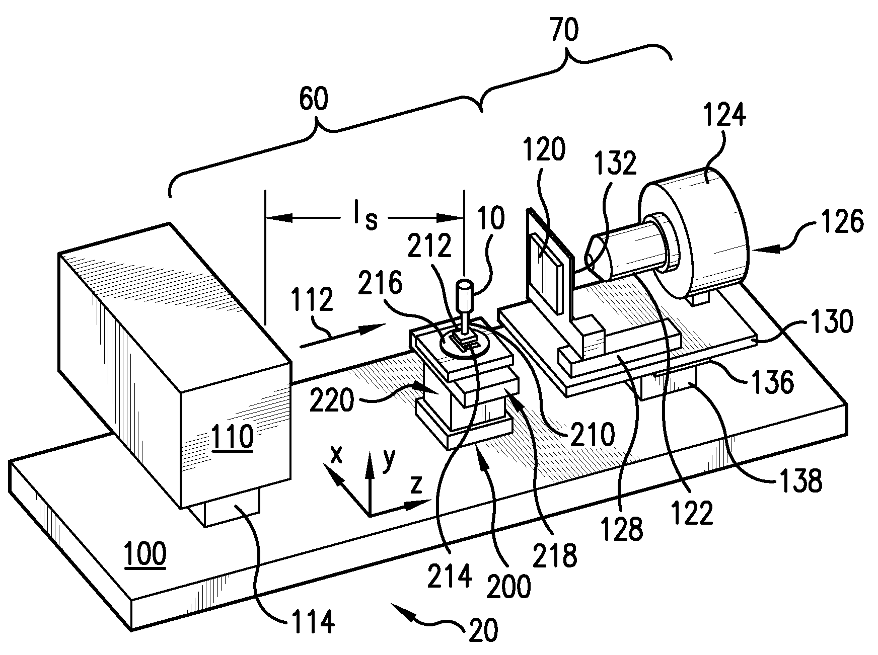
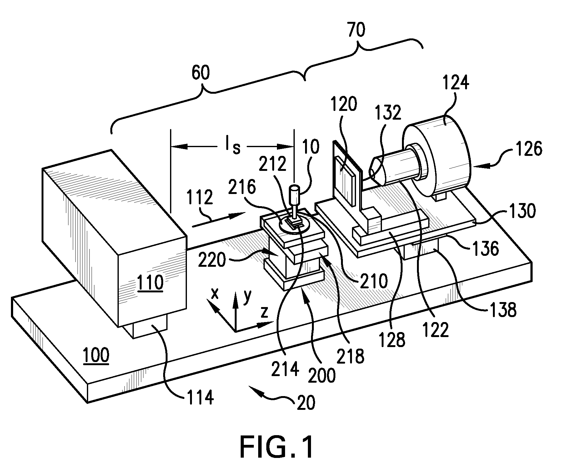
[0035]FIG. 1 illustrates an x-ray imaging system that has been constructed according to the principles of the present invention.

[0036]Specifically, the x-ray imaging system 20 comprises an optical table 100. This provides a stable, planar surface on which the components of the imaging system 20 are secured.

[0037]An x-ray source 110 is secured to one end of the optical table 100. It generates an x-ray beam 112, which is typically a diverging x-ray beam as is common in these x-ray projection systems.

[0038]In one example, the x-ray source 110 is a rotating-anode type, with a tungsten target, but in other embodiments, the target comprises molybdenum, gold, platinum, silver, or copper.

[0039]In still other examples, the source 110 is a synchrotron radiation x-ray source.

[0040]In the preferred embodiment, the x-ray source 110 can be moved relative to the optical table 100. Specifically, an x-axis source motion stage 114 is preferably provided in order to adjust the position of the x-ray so...


PUM

PropertyMeasurementUnit
diameteraaaaaaaaaa
diameteraaaaaaaaaa
distanceaaaaaaaaaa

Abstract

A projection-based x-ray imaging system combines projection magnification and optical magnification in order to ease constraints on source spot size, while improving imaging system footprint and efficiency. The system enables tomographic imaging of the sample especially in a proximity mode where the same is held in close proximity to the scintillator. In this case, a sample holder is provided that can rotate the sample. Further, a z-axis motion stage is also provided that is used to control distance between the sample and the scintillator.

Description

RELATED APPLICATIONS[0001]This application is a continuation of copending U.S. application Ser. No. 11 / 035,749, filed on Jan. 14, 2005, which claims the benefit under 35 USC 119(e) of application Ser. No. 60 / 536,385 filed on Jan. 14, 2004, both of which are incorporated herein by this reference in their entirety.BACKGROUND OF THE INVENTION[0002]Since its discovery, the ability of x rays to penetrate through material has been exploited extensively, such as in non-invasive and non-destructive imaging in medical and industrial applications.[0003]For example, a number of manufacturers have developed imaging tools for failure analysis of integrated circuit (IC) packaging that take advantage of the penetrating power of hard x rays with tens to hundreds of kilo electron-Volts (keV) energy. These x-ray inspection tools typically provide resolutions on the order of tens of micrometers. This is sufficient for inspecting most large features in IC packages. They provide sample mounting mechanis...

Claims


Application Information

Patent Timeline
Patent Type & Authority Patents(United States)
IPC IPC(8): G01N23/20H05G1/00A61B6/08
CPCG01N23/20A61B6/508G01N2223/505G01N2223/6113G01N23/044
Inventor YUN, WENBINGSCOTT, DAVID DEANTRAPP, DAVID R.DUEWER, FREDERICK WILLIAMWANG, YUXIN
Owner CARL ZEISS X RAY MICROSCOPY
Why Eureka
Try Eureka